Advanced Features of EHB-CB
Intermediate Hierarchy Filtering
This feature is sold as a separate option on request and is not part of the standard EHB-CB tool. There is the request, that the interactive ASCET model of a function only contains sub hierarchies for which an image screenshot in the documentation is also available. However, to allow a continuous model navigation, also intermediate hierarchies without documentation has to be handled and shown in an appropriate way.
Example:
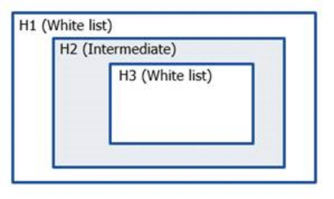
White list [H1, H3]: Hierarchies whose image screenshots are present in the documentation.
Intermediate list [H2]: Hierarchies whose parent [H1] is a white listed hierarchy and whose one or more child hierarchies [H3] are also white listed. But H2 is not present in the documentation.
To allow now a model navigation from H1 to H3, H2 will be still shown, but its contents of it are filtered out to maintain minimalist information.
Without the option -ihf, only H1 will be part of the interactive model.
The ihf feature is only an emergency solution and has some limitations. The better way would be to use the build-in view mechanisms of ASCET upfront, see chapter View Concept
JSON Configuration Format
The configuration is supplied as a JSON file and referenced by the -ihf command-line option during container generation.
Each JSON entry maps one model or source file (for example, .axl, .mdl, .slx) to a list of hierarchies that should be retained in the interactive model view.
[
	{
		"../Lcc/lcc.axl": [
			"LambdaControl.Main",
			"LambdaControl.Main.Two-point-controller",
			"LambdaControl.Main.PID-Controller",
			"PID_Limit_AWU.Main"
		]
	},
	{
		"../t2t/T2t.mdl": [
			"T2t.T2t_mdl",
			"T2t.T2t_mdl.ThrottleValveControl",
			"T2t.T2t_mdl.WastegateControl"
		]
	}
]
Concept
-
Each object key represents a model or subsystem file path relative to the container build input directory.
-
Each array value lists the fully qualified hierarchy names (using dot notation) that should remain visible even if no graphical documentation exists.
-
The specified hierarchies are treated as intermediate levels and will be displayed in Navigator as structural nodes for better traceability.
|
Even if a hierarchy has no image or documentation, if it is listed in the IHF JSON, it will appear as a navigable node in the final container. |
Using the Configuration
Please refer EHB-CB usage in General
|
Known limitations:
If the ASCET model contains about 1000 references (Class instance entries) the time is increased by a factor of 5 and if model has more than 150 *.amd file entries the time is increased by a factor of 10. |
Root Level Skipping
Typically, an ASCET, ASCET-DEVELOPER or Simulink model starts with some first wrapping hierarchies, which were of no interest to the EHB-NAV user. In addition, for the seamless function wallpaper feature, it just wastes space and makes it complex. Therefore, EHB-CB provides the flexibility to change the entry level of a model type (ASCET, ASCET-DEVELOPER, SIMULINK) by using a JSON configuration file.
Considering the example below without skipping:
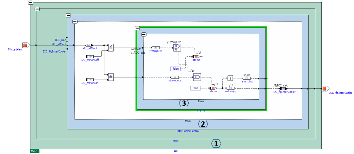
Same example with skipping of the first two root levels:
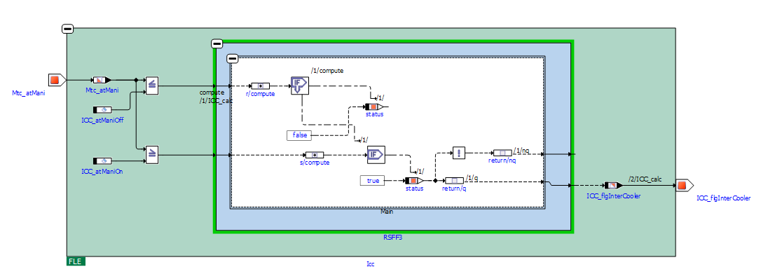
With the JSON file shown below (plain ASCII format), all ASCET models in the container are opened with its 2nd and ASCET-DEVELOPER, SIMULINK with 1st level.
{
	"rootLevel": {
		"ASCET": "2",
		"Simulink": "1",
		"ASCET-DEVELOPER": "1",
	}
}
Conditions for level skipping:
-
Level exceeds
In case the level specified in JSON file is exceeding the one available in the model, then the tool stops at the last available level in the model. -
Multiple sub levels in parallel
In case of multiple expandable sub levels exist in an upper level, the tool stops at the immediate parent level, as there is a conflict of unambiguousness. In such cases, root-level jump option can be used. See chapter Root Level Jump.
To activate this feature, the command line option -rootlevel “path_to_jsonfile\name.json” has to be provided.
A sample file is available in the examples sub folder of the EHB-CB installation directory. (..\examples\configuration\RootLevel.json)
|
For the C-Code models, root-level skip cannot be applied. |
Root Level Jump
In order to change the entry level of ASCET (Classic) and Simulink models, when there are multiple expandable sub levels in the model, Root Level Jump configuration can be used.
Consider the example below without jumping any levels.
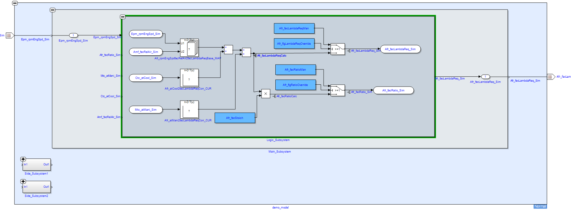
When root level jump is applied, the model would directly start from the specified model path, eliminating the parent levels even if the parent levels contain expandable sub levels:
The JSON configuration file could look like this. Here, either the exact model path or a regex pattern of the model path could be provided, which is the desired starting point for the model in EHANDBOOK:
{
	"rootLevelJump":[
		"Main_.*/Logic_.*"
	]
}
Multiple regex patterns can also be provided. In that case, the first matching pattern with the model will be applied for root level jump
For example, in the following JSON, both the patterns are valid and represent different levels of the model. Here, the first pattern will be considered:
{
	"rootLevelJump":[
		"Main_.*/Logic_.*",
		"Main_.*"
	]
}
Condition for root level jump:
If a regex pattern matches multiple blocks at the same model level, root level jump will not be applied.
To activate this feature, the command line option -rootlevel “path_to_jsonfile\name.json” has to be provided.
A sample file is available in the examples sub folder of the EHB-CB installation directory. (..\examples\configuration\RootLevel.json)
|
Container Encryption
Encrypted containers can be generated by using the command parameter -epwd or -epwdf. The password can be passed either in the command line e.g. -epwd "qwertz" or within a password file e.g. -epwdf ./my_password_file.txt. If using a separate password file, the password must be surrounded with % characters e.g. %my_secret% as content of the password file. The password file is deleted after container encryption.
The password should satisfy the following credentials:
-
Password length: minimum 4; maximum 255 characters
-
Password characters: alphanumeric, special characters are allowed
-
Password pattern: No special pattern is required
The container gets the new file extension .ehbcrypt. It can be opened in the EHB-NAV in the same way. But after section of the container file, the user will be prompted for the correct password to be typed in.
ClickPic
EHANDBOOK Container-Build is capable to generate graphics out of a model and link it with its corresponding interactive model hierarchy. In addition, these graphics are linked between each others in the Function Documentation Window in EHB-NAV, the so called ClickPic navigation feature. To visualize these graphics, some special keywords have to be added in the text source files.
RTF input files:
[ehbmodelref]
Model hierarchy path in text style of type “Caption”
AsciiDoc input files:
ehbmodelref::model_path[image_title]
ASAM input files:
In FSX, the FIGURE’s <SHORT-NAME> for the model graphic contains the model hierarchy path directly in a mandatory format i.e. “X.Y.Z”.
More details about this can be found in ASAM Specification.
To allow EHB-CB generated graphics and ClickPic containers must be generated by using the command parameter -gensvg, otherwise this feature will not work!
NOTICE
Incomplete, wrong or differing representation of model screenshots and interactive models from source data.
During the conversion of ASCET models, Simulink/Stateflow models or C-Code to interactive models and/or SVG graphics, the generated outputs may differ from the original model visualizations. As C-Code is written in textual form while interactive models are graphical diagrams, the semantic and interpretation can differ.
The following deviations between the model and the EHANDBOOK Container content may occur:
-
Missing or wrong graphics
-
Wrong targets on linked graphics
-
Wrong model links
-
Wrong model hierarchy links
-
-
For C-Code visualizations, different interpretations and semantics
Possible root causes of these deviations are:
-
Link specification in input text does not match to model hierachy path
-
Referenced model/source files are missing
-
Matlab connection for mask generation in Simulink was broken,
-
EHB-CB tool error due to internal error or unsupported source content
-
Technical limitations, especially for representing C-Code as graphical visualization
To identify deviations:
-
Check the entries in the log file of the generated EHANDBOOK Container for Warnings and Errors
-
Check the links between SVG graphics and interactive models in the EHANDBOOK Container
It is the responsibility of the creator of the EHANDBOOK Container to check the log files generated by EHANDBOOK Container-Build and to check the outputs for wrong model references and initiate the correction in the sources.
To ensure consistency and mitigate limitations:
-
Check the release notes and the known issues of EHANDBOOK Container-Build as well as EHANDBOOK-NAVIGATOR.
-
Compare the C-Code source code with the its graphical representation in EHANDBOOK-NAVIGATOR.
View Concept
For know-how protection purposes, ASCET allows designing the models for different views, e.g. it is possible to hide some element for a defined view. EHB supports this concept. With the command line option -viewtype “ViewName” you are setting, for which view the model and its screenshots should be generated. The command line option -ascetview “config-file.xml” locates the file, where for every view name the corresponding model appearance is configured in a given format.
You can export a view file from ASCET:
Tools (ASCET Main Window) Views → Select the view names to be exported (multiple selection allowed) → Click Export button and choose destination and name of the file.
The following elements are supported in EHB for the views:
| ASCET View contents | Support in EHB |
|---|---|
BDE Settings Show Unused Sequence Calls Show Used Sequence Calls Show Graphical Comments Show Process Name Locals |
All settings supported |
Default settings for Elements As Line Contour |
Element properties of type ‘Implementation Cast’ is supported only |
Documentation Settings |
Not Implemented |
In ASAM-CCX, you can also define a view name in the tag <SD GID="view">Name</SD>. It supersedes the command line option -viewtype. For details, please refer to the document ASAM Format Specification for EHB.
|
The view name provided by -viewtype has to match to the view name specified in corresponding view file, otherwise no view is applied. |
For c-code the same method is used with the parameter -ccodeview “config-file.xml”. Here the same xml format as for ASCET is used, but you can only specify, if process sequence calls are visible in the interactive model or not. These calls are showing the computation order of the c-code.
Sample files are available in the examples sub folder of the EHB-CB installation directory. (..\examples\configuration\AscetFiguresView.xml, CCodeViews.xml)
Configuration of details shown for Simulink subsystem-based blocks
For know-how protection reasons or for a better readability, Simulink blocks that are based on subsystems can be specified as non-expandable for interactive models in EHANDBOOK-NAVIGATOR during EHANDBOOK Container generation. To enable the global configuration feature, the command line option -simulinkview (CB) or -simulinkviewfile (UGG) that takes "path_to_jsonfile\name.json" as argument is used. The JSON file specifies the behavior of the blocks then, see samples below.
Makes referenced blocks with masks non-expandable (e.g. libraries):
{
	"GlobalView": {
		"HideContents": [
			{
				"BlockType": "Reference",
				"Simulink.Mask": "true"
			}
		]
	}
}
Makes all subsystems with masks non-expandable:
{
	"GlobalView": {
		"HideContents": [
			{
				"BlockType": "SubSystem",
				"Simulink.Mask": "true"
			}
		]
	}
}
Makes any masked Simulink block non-expandable:
{
	"GlobalView": {
		"HideContents": [
			{
				"Simulink.Mask": "true"
			}
		]
	}
}
Makes any subsystem non-expandable:
{
	"GlobalView": {
		"HideContents": [
			{
				"BlockType": "SubSystem"
			}
		]
	}
}
A sample file is available in the examples sub folder of the EHB-CB installation directory. (..\examples\configuration\SimulinkGlobalView.json)
|
The feature above works only if the key word Simulink.Mask is used inside the model file. This is the case for MATLAB 2012b onwards. For older versions (2012a and below) the key word MaskDisplay is used, which is currently not supported. |
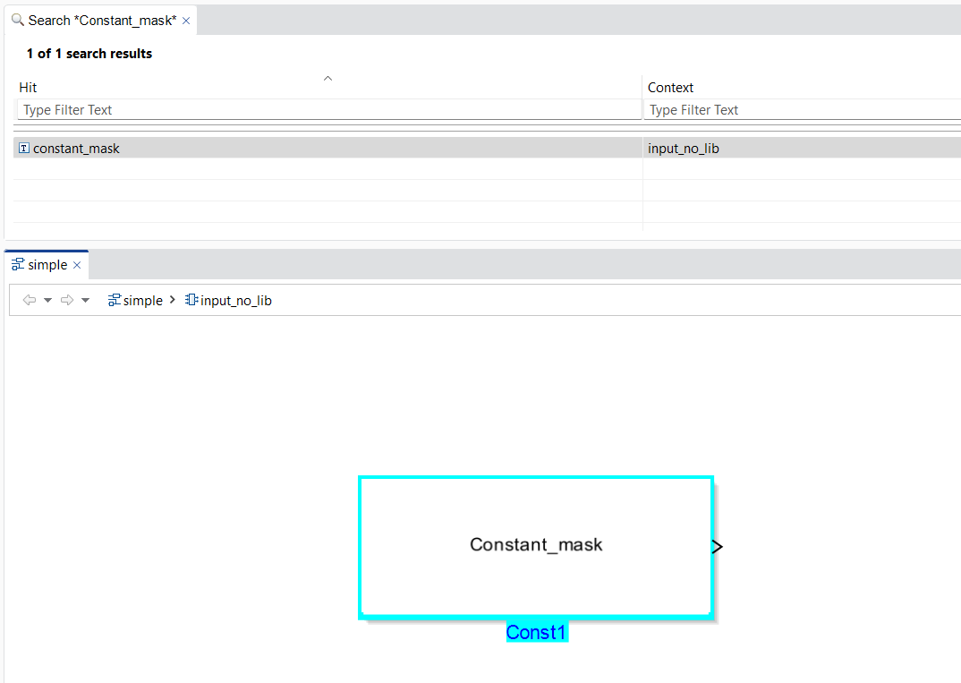
Support for mask parameters in Simulink Constant blocks
In a Simulink 'Constant block', the block parameter 'Constant value' can be exposed as a mask parameter. For this feature to work, the mask parameter 'Name' must be set to 'Value'. The parameter 'Value' corresponds to the block’s 'Constant value', which can be configured by the user.
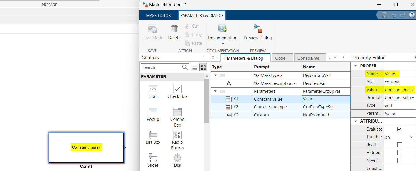
When this configuration is used, the block becomes interactive in EHANDBOOK.
-
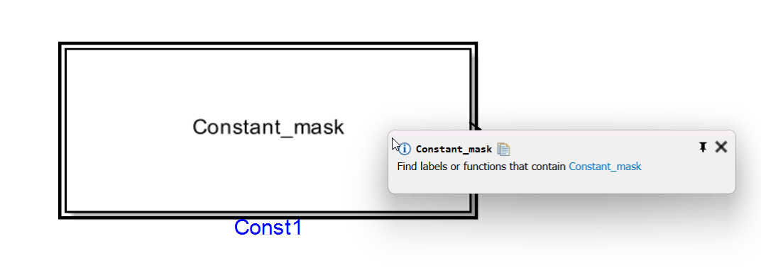
Clickable Blocks: The entire area of the configured 'Constant block' becomes clickable.
-
Label Popup: Clicking the block opens a label popup displaying the configured 'Constant value'.
-
Searchable Labels: The 'Constant value' is indexed and can be found using the search functionality.
|
This feature only works for Simulink 'Constant' blocks. Known limitations:
|
Model Depth Skip
Model depth skip can be used to convert all Simulink models till a particular model hierarchy level starting from the root level. This may be useful, to hide know-sensitive information in deeper model hierarchies.
For this feature, the same command line parameter -simulinkview and JSON file as for the feature above is used. In this JSON file, an additional section “ModelDepth” with the required level can be provided:
{
	"GlobalView": {
		"ModelDepth" : 5
	}
}
“ModelDepth” value must be in integers.
In this example, all Simulink models within a container will be converted up to 5 levels from the root level.
Label Amendment
Several features of EHANDBOOK-NAVIGATOR are based on the notion that the label names visible in interactive models correspond to label names in an A2L file. Also the function overview in NAV works purely name based. This means, the variable name from an exporting function has to match to the name of the importing function.
There can be cases, however, where the strings that are visible in an ASCET or Simulink model do not directly correspond to an A2L label name or match between functions. In this case, features like label pop-up, INCA visualization or function overview will not work in EHB-NAV.
By means of amending the names of labels in interactive models and the generated screenshots, models and screenshots can be "patched" such that the visible strings do match the expected A2L label names. It works in such a way that during the generation of an interactive model from a source ASCET or Simulink model the strings resembling label names are analyzed and transformed according to a specific set of rules. The rules are specified in a JSON file and passed via an argument to EHB-CB or UGG. The command line parameter is
-labelamendment with “path_to_json_file/name.json” as argument.
The rules for renaming are specified in a JSON file format:
Exact Replacements
Exact replacements are specified as key-value pairs of strings in rule groups marked with the key word "exact". They work straight-forward - the string in the key is replaced by the string in the value:
“Original_Name” : “New_Name”
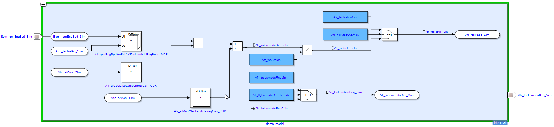
Here’s an example for a set of exact replacement rules:
{
"exact": {
"Epm_rpmEngSpd_Sim" : "Epm_rpmEngSpd_Sim_changed",
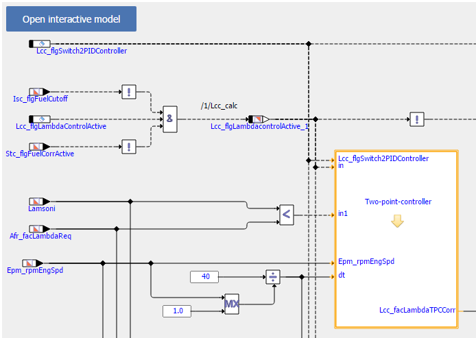
"Two-point-controller" : "Two-point-controller_changed",
"Lamsoni_Sim" : "Lamsoni_Sim_changed"
}
}Pattern-based Replacements
Pattern-based replacement are specified as key value pairs of strings in rule groups marked with the key word "pattern". The keys make use of regular expressions to match strings that shall be amended. The values denote replacement strings. The latter can make use of the match groups defined in the regular expression.
“Target_Pattern” : “Substitude_Pattern”
Here’s an example for a set of pattern based replacement rules:
{
	"pattern": {
		"(.*)_write": "$1",
		"read_(.*)": "$1",
		"read_(.*)_write": "$1",
		"(.*)_middle_(.*)": "$1_$2"
	}
}
If the single character ‘.’ is used for a regular expression it must be escaped by ‘\\’
"prefix_(.*)\\.postfix" : "$1_postfix",
Here a sample Internet page with further information about regular expressions in general and online testing possibilities: https://freeformatter.com/regex-tester.html
Order in which replacements are applied
The order of rules as well as rule groups is of relevance. Rules within a rule group are applied in sequence. The same applies to rule groups; they are also applied in the sequence specified in the JSON file. Through this, even multiple rules can be applied during a transformation.
A sample file is available in the examples sub folder of the EHB-CB installation directory. (..\examples\configuration\LabelAmendment.json)
|
On application of label amendment to model hierarchies, clickPic for backward navigation and “open interactive model” does not work! |
Passing Simulink library paths to EHB-CB
Two command line parameters could be used to provide SIMULINK library paths as input for the container generation.
simlib
Provide folder paths enclosed within double quotes separated by commas. Example:
-simlib "path1,path2,path3"
simlibfile
Provide path to json file containing paths to all libraries required. Example:
-simlibfile "path_to_json_file"
The key property in the json file used is "libraryPaths". Here’s an example of the JSON file:
{
	"libraryPaths": [
		"path1",
		"path2",
		"path3"
	]
}
Function Overview Diagram
EHB-CB is capable to generate a Function Overview Diagram with all input- and output signals automatically. Besides one single function, there are also multiple functions possible, showing the dependency and relation between them.
The generated Function Overview diagram will appear in EHB-NAV in the Function Documentation Window with a new navigation button named “Open function overview”. On click of this button, the model explorer tab opens with combined Function Overview of the functions appearing the image.
The separate chapters Function Overview Diagram in the TOC of EHB-NAV are generated by default without any additional configurations during container generation, independent of this feature.
Required changes to achieve this functionality are described in the separate documents RTF format Specification and AsciiDoc format Specification for directory based EHB-CB and in ASAM format Specification for the ASAM based EHB-CB.
|
Creating function overviews with > 30 functions is not advised as all the functions might not fit into canvas. |
Structure Data Type Support
EHANDBOOK supports configuration of structure data types for Simulink. Structures are mapped to Simulink buses. Structures can be defined in MDX following the MDX specification. For details please refer to the document ASAM Format Specification for EHB-CB.
Configuration for C-Code Visualization
The visualization of C-Code as block diagram can be customized through several configurations. These can be adapted in such a way that the program logic is represented more precisely and that the graphical visualization can be understood more easily.
The configuration options are provided through a central configuration file in XML format. The configuration file is to be passed using the command-line option -ccodemeta with
“path_to_meta_file/name.xml” as argument.
The following shows the XML template for the C-Code configuration options.
<?xml version="1.0" encoding="UTF-8"?>
<functionmetadata:FunctionMetadataRoot
	xmi:version="2.0"
	xmlns:functionmetadata="http://www.etas.com/ehandbook/functionmetadata"
	xmlns:xmi="http://www.omg.org/XMI">

	<globalConfiguration
		libraryPath="../lib"
		inlineFunctions="true"
		simplifyDiagram="true"
		generateHierarchies="true"
		maxIterationForDataflowAnalysis="50000"/>

</functionmetadata:FunctionMetadataRoot>
The configuration options are described in the following:
libraryPath
For a given ECU function, having a set of C-files with implementations, the C-functions call other C-functions as sub-routines or service routines.
A suitable way to arrange such ECU specific C-files and global sub-routines is to configure where C-files for ECU functions are placed, and where the global sub-routines are placed.
This configuration specifies the location of all such global sub-routines or other C functions which could be present in a true either .c files or .h files.
These files typically contain helper or utility functions for the ECU specific C-files.
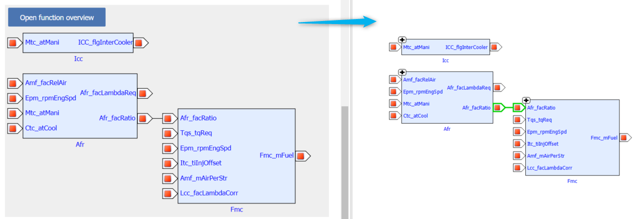
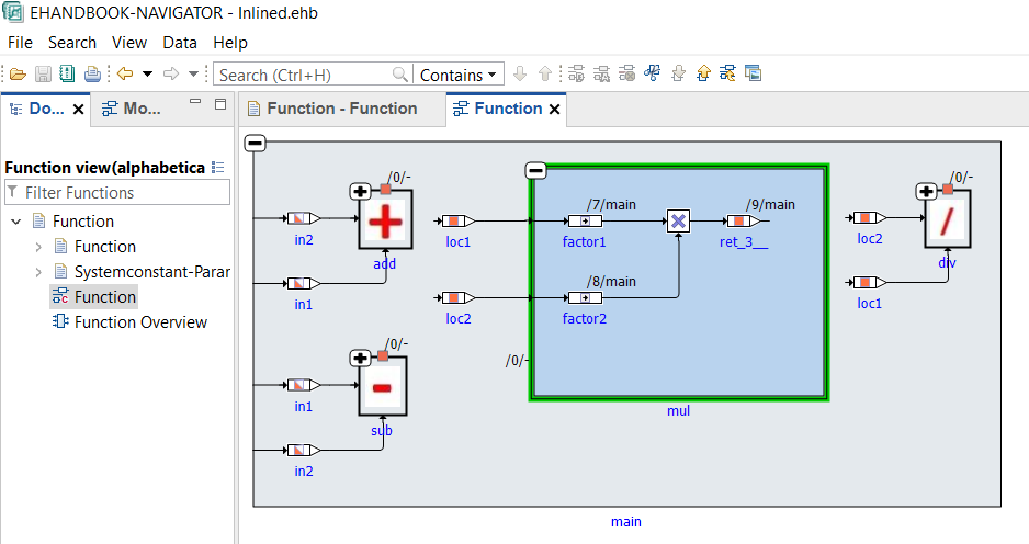
inlineFunctions
This configuration can be set to true/false in order to enable/disable the graphical inlining of called C-functions into the context of the calling C-functions.
Default setting: inlineFunctions=false
If set to true, the model visualizes the called function (e.g. global sub-routine/other C functions) as an expandable block within the block of the calling function.
|
For clearness, the Inlined C-functions are removed from the top level. Therefore, no model screenshots for these functions can created via -gensvg. |
Example: The C-function mul is called from C-function main.
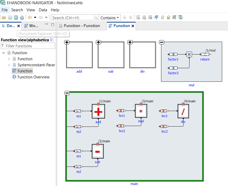
If set to false, the model visualizes the called function (e.g. global sub-routine/other C functions) as non-expandable block within the block of the calling function. Note that the called functions are visualized as top-level expandable blocks.
This configuration can be used to obtain visualizations of C-libraries, for example.
Example:
simplifyDiagram
This configuration takes in a true/false to enable/disable simplification of C-Code model. When enabled, unused variables and code from visualization are omitted, thereby decluttering and consequently simplifying the model visualization. However, the simplification can be disabled to view the actual model aiding in verifying the correctness of the model in comparison to the original source code, if required.
Default setting: simplifyDiagram=true
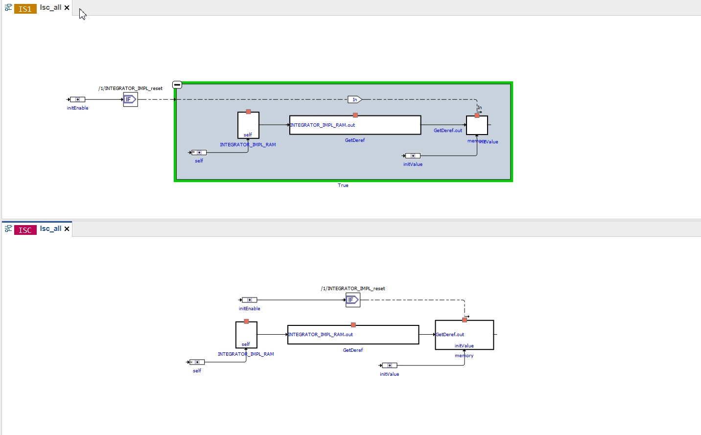
generateHierarchies
This configuration takes in a true/false to enable/disable artificial hierarchies in C-Code model. When enabled, artificial hierarchies are placed to logically group the elements. However, it could be disabled to have no hierarchies and view the model as it is in the original source code.
Default setting: generateHierarchies=true
Below, is an image depicting artificial hierarchies being created in the upper part. Here “True” which is expanded to show the contents, is an artificial hierarchy. The bottom part of the image shows C-code model with hierarchy generation being disabled, hence appears flat.
maxIterationForDataflowAnalysis
C-Code is converted to a data structure, which can be visualized as block diagram.
A part of the underlying algorithm is to calculate the connections between the blocks that represent the variables and operators of the C code functions. This is referred to as “Dataflow Analysis”.
maxIterationForDataflowAnalysis is a configuration parameter to tweak the calculation of the connections through an iterative Dataflow Analysis.
-
A too high value can lead to high memory consumption and longer runtime than necessary in order to calculate all connections.
-
A too low value can result is unconnected blocks due to missing connections. The algorithm terminates before all connections have been calculated.
The value should be chosen such that it represents the minimal number of iterations even for the most complex C-code sources of a given ECU program.
Default setting: maxIterationForDataflowAnalysis=50000
A sample file is available in the examples sub folder of the EHB-CB installation directory. (..\examples\configuration\CCodeConfig.xml)
|
When maxIterationForDataflowAnalysis is exceeded, an "Error" will be logged in the log file. |
NOTICE
Incomplete, wrong or differing representation of model screenshots and interactive models from source data.
During the conversion of ASCET models, Simulink/Stateflow models or C-Code to interactive models and/or SVG graphics, the generated outputs may differ from the original model visualizations. As C-Code is written in textual form while interactive models are graphical diagrams, the semantic and interpretation can differ.
The following deviations between the model and the EHANDBOOK Container content may occur:
-
Missing or wrong graphics
-
Wrong targets on linked graphics
-
Wrong model links
-
Wrong model hierarchy links
-
-
For C-Code visualizations, different interpretations and semantics
Possible root causes of these deviations are:
-
Link specification in input text does not match to model hierachy path
-
Referenced model/source files are missing
-
Matlab connection for mask generation in Simulink was broken,
-
EHB-CB tool error due to internal error or unsupported source content
-
Technical limitations, especially for representing C-Code as graphical visualization
To identify deviations:
-
Check the entries in the log file of the generated EHANDBOOK Container for Warnings and Errors
-
Check the links between SVG graphics and interactive models in the EHANDBOOK Container
It is the responsibility of the creator of the EHANDBOOK Container to check the log files generated by EHANDBOOK Container-Build and to check the outputs for wrong model references and initiate the correction in the sources.
To ensure consistency and mitigate limitations:
-
Check the release notes and the known issues of EHANDBOOK Container-Build as well as EHANDBOOK-NAVIGATOR.
-
Compare the C-Code source code with the its graphical representation in EHANDBOOK-NAVIGATOR.
Support for Preprocessor Macros in C-Code
EHB supports preprocessor macros used in C-code. These macros can influence the model behavior and need to be handled properly for accurate representation in the EHANDBOOK.
The values for preprocessor directives can be provided in two ways:
-
Defined directly within the C-code (e.g., using #define statements).
-
Supplied through metadata (.mdx) file
This ensures that the preprocessing logic is correctly resolved during the container build process and reflected in the interactive model view.
Label Table Configuration
Per FC, there is always one generic chapter with the default name Systemconstant-Parameter-Variable-Classinstance-Structure. This chapter contains the tables for all the elements, which are specified in the corresponding MDX, ARXML or xls-file. The name of the chapter and the appearance of the tables can be configured with the command line parameter -tableconfig “file_path\file.json”. The JSON file defines the view as follows:
{
	"chapter": "Name of the chapter in EHB-NAV",
	"tables": [
		{
			"title": "Variable",
			"filters": [
				{
					"id": "ehb_element_type",
					"value": "ehb_variable"
				}
			],
			"columns": [
				{
					"title": "Name",
					"id": "ehb_name",
					"width": "20%"
				},
				{
					"title": "Description",
					"id": "ehb_desc",
					"width": "40%"
				},
				{
					"title": "Unit",
					"id": "Unit",
					"width": "10%"
				},
				{
					"title": "Data Type",
					"id": "Type",
					"width": "10%"
				},
				{
					"title": "Mode",
					"id": "ehb_mode",
					"width": "20%"
				}
			]
		},
		{
			"title": "Calibration/Parameter",
			"filters": [
				{
					"id": "ehb_element_type",
					"value": "ehb_parameter"
				}
			],
			"columns": [
				{
					"...": "..."
				}
			]
		}
	]
}
The “tables”: [] section defines the appearance of each table.
Each table begins with a title entry: “title”: “Name of the table title in EHB-NAV”
In the section “filters”: [ “id”: “ehb_element_type” you specify the table element type by defining one of the following key words for “value”:
| Type of table | Matching key words for “value”: “…” | Corresponding entry in xls | Corresponding entry in MDX | Corresponding entry in ARXML |
|---|---|---|---|---|
Variables Parameters System Constants Class Instances Sender Receiver Interface Parameter Interface Client Server Interface |
“ehb_variable” “ehb_parameter” “ehb_system_constant” “ehb_class_instance” “ehb_variable” “ehb_parameter” "ehb_autosar_csport" |
Sheet “Signal” Sheet “Calibration” N.A. N.A. N.A N.A N.A |
<SW-VARIABLE> <SW-CALPRMS> <SW-SYSTEMCONST> <SW-CLASS-INSTANCE> N.A N.A N.A |
N.A N.A N.A N.A <SENDER-RECEIVER-INTERFACE> <PARAMETER-INTERFACE> <CLIENT-SERVER-INTERFACE> |
In the section “columns”: [ ] per column entry, a “title” & “id” pair defines the column content:
“title”: “column name” defines the name of the column in EHB-NAV
“id”: “Input source value from MDX, ARXML or xls to be shown”.
“width”: Defines width of the table column that can be configured in PDF. “width” is denoted in percentage.
For the “id” values, fixed pre-defined key words are used:
| Key word for “id”: “…” in JSON | Corresponds to column in xls | Corresponds to key word in MDX |
|---|---|---|
“ehb_name” |
“Name” |
<SHORT-NAME> |
“ehb_desc” |
“Description” |
<LONG-NAME> |
“ehb_mode” |
“Xref” |
No tag avail. |
“ehb_access” |
N.A. |
<SW-CALIBRATION-ACCESS> |
“ehb_data_type” |
“Class” |
<BASE-TYPE-REF> |
“ehb_reference” |
N.A. |
No tag avail. used for class instance table only |
“ehb_category” |
N.A. |
Entry in <CATEGORY> |
For other element properties, defined in further column entries in the xls file, the identical name is used in the JSON file as “id” value also. The same applies for MDX entries used for properties.
You can define as many “title” & “id” pairs as you want, but you have to consider the page width in EHB-NAV and especially in PDF if printing is required.
The order of the “title” & “id” pairs in the JSON file are defining the order of the columns in EHB-NAV from left to right.
The order of the tables in the JSON file are defining the order of the tables in EHB-NAV from top to bottom.
You can divide the tables into different ones by adding additional filter attributes.
"title": "Input Variables",
"filters": [
	{
		"id": "ehb_element_type",
		"value": "ehb_variable"
	},
	{
		"id": "ehb_mode",
		"value": "import"
	},
	{
		"...": "..."
	}
]
A filter criterion can be configured as “id” & “value” pairs
“id”: “type” defines the type for the filtering
“value”: “value of type” defines the content of type, which should match the filter criteria
For “type” and “value” fixed pre-defined key words are used:
| Key word for “id”: “…” | Matching key words for “value”: “…” | Corresponding entry in xls | Corresponding entry in MDX | Corresponding entry in ARXML |
|---|---|---|---|---|
“ehb_mode” |
“import” “export” “local” |
IN OUT LOC |
<IMPORT> <EXPORT> <SW-FEATURE-OWNED-ELEMENT-SET> |
<R-PORT> <P-PORT> N.A |
For other element properties required for as filter criterion, the corresponding column entry in the xls file can be used. Here the identical column name is required in the JSON file as “id”: “type” also. In addition, the text entry in the column must be identical in the JSON “value”: “text entry”. The same applies for MDX and ARXML entries used for filtering.
Multiple filter criteria can be used. They are combined as logical AND, e.g. element_type=variable & mode=exported & type=float.
You can define as many tables as you want, with any combination of filters, but limited to the pre-defined key words like ehb_element_type and ehb_mode.
Multiple values filter
Additionally values from multiple columns can be filtered by the key named "values". Here, multiple values which shall be included in the table entry can be added. Depending on the use case, either the key "value" or the key "values" or both can be used.
In the below example, the table can have the entries which match the category as R-PORT or STRUCTURE or VALUE.
"title": "Input Variables",
"filters": [
	{
		"id": "ehb_element_type",
		"value": "ehb_variable"
	},
	{
		"id": "ehb_mode",
		"value": "import"
	},
	{
		"id": "ehb_category",
		"values": [
			"R-PORT",
			"STRUCTURE",
			"VALUE"
		]
	}
]|
It is recommended to use "value" for filtering exactly one value. In case of multiple values required to be included in the filter, the key word "values" to be used. If both key words ("value" and "values") are used then filtering will be a combination of both. |
All key words and value entries are handled case insensitive but have to be exact. There is no error handling for wrongly spelled entries.
A sample file is available in the examples sub folder of the EHB-CB installation directory. (..\examples\configuration\TableConfiguration.json)
Label Configuration
In a model, you have multiple possibilities how to name a label. The tools ASCET 6 and ASCET-DEVELOPER provide certain options to configure the composition of an element name. E.g. the element name can be appended with their parent elements and the order of the name parts can be defined. So the name may differ from the name in the a2l file and MCD features like INCA connectivity will not work.
Therefore, EHB-CB provides the flexibility to configure the label names by using a JSON configuration file (plain ASCII, UTF8 format), so that it matches the names in A2L file. There is one single JSON file with individual configuration possibilities per model type (ASCET 6, ASCET DEVELOPER, Simulink) and also a common configuration for any model type.
See sample LabelConfig.json in the sub folder .\examples\configuration of your EHB-CB installation directory.
|
Please ensure, that the configuration parameters in ASCET and in the JSON file are matching. Otherwise labels from a2l-file or from INCA could not be shown in EHB-NAV. |
For all model types
EHB-CB provides an option to add configurable and invisible label names to blocks for Simulink, ASCET, ASCET-DEVELOPER and C-Code models. Label names can be assigned directly based on the block names (Exact replacement) or based on block name patterns (Pattern-based replacement). These replacement rules can be defined under the keyword "Common" in the label configuration JSON file.
Exact replacements
Exact replacements are specified as key-value pairs of strings in rule groups marked with the key word "exact". They work straight-forward - the string in the key is replaced by the string in the value:
“Original_Name” : “New_Name”
With the JSON file shown below all blocks with name "Afr_rpmEngSpd" will have the label name "Afr_rpmEngSpd_modified" and all blocks with the name "Two-point-controller" will have the label name "Two-point-controller_changed".
{
	"Common": {
		"exact": {
			"Afr_rpmEngSpd":"Afr_rpmEngSpd_changed",
			"Two-point-controller":"Two-point-controller_changed"
		}
	}
}
If the same key is used again with a different value, the latest value is considered.
Pattern-based replacements
Pattern-based replacements are specified as key value pairs of strings in rule groups marked with the key word "pattern". The keys make use of regular expressions to match strings that shall be amended. The values denote replacement strings. The latter can make use of the match groups defined in the regular expression.
“Target-Pattern” : “Substitute-Pattern”
Here’s an example for the Pattern-based replacement rules:
{
	"Common": {
		"pattern": {
			"(.*)_write": "$1",
			"read_(.*)": "$1"
		}
	}
}
Here, the sequence of patterns is important. If there are multiple patterns matching with a label name, the first match will be applied. If the single character ‘.’ is used for a regular expression it must be escaped by ‘\\’
"prefix_(.*)\\.postfix" : "$1_postfix",
Here a sample Internet page with further information about regular expressions in general and online testing possibilities: https://freeformatter.com/regex-tester.html
Combination of Exact and Pattern-based replacements
A combination of Exact and Pattern-based label configuration is also possible. In case there is an "Exact replacement" already provided for a block and there is also a match found based on the pattern, the exact label name will take the precedence. For example, in the below JSON file there is a label name already provided for "Afr_rpmEngSpd_write" in the "Exact replacement" section. But it also matches the pattern "(.*)_write". In this case, the label name will be "Afr_rpmEngSpd_changed".
{
	"Common": {
		"exact": {
			"Afr_rpmEngSpd_write": "Afr_rpmEngSpd_changed",
			"Two-point-controller": "Two-point-controller_changed"
		},
		"pattern": {
			"(.*)_write": "$1",
			"read_(.*)": "$1",
			"read_(.*)_write": "$1",
			"(.*)_middle_(.*)": "$1_$2"
		}
	}
}|
EHANDBOOK also provides an option to configure label names for individual model languages. When the "Common" label configuration is used along with any model specific label configuration, the "Common" label names will take the precedence. |
For ASCET-DEVELOPER
The element name could be placed first or last, when appended with their parent elements or package names could be omitted.
With the JSON file shown below (plain ASCII, UTF8 format), ASCET-DEVELOPER models in the container will have the element name placed last and will not be appended with the package name. This is also the default, if no label configuration is provided.
{
	"ASCET-DEVELOPER": {
		"elementNameFirst": false,
		"includePackageName": false
	}
}
For example, a class element “signal” within class “Component”, placed inside package “components” would have the name as in the below table according to the various combinations provide in JSON file. This name is used to connect to INCA on EHANDBOOK-NAVIGATOR.
includePackageName |
elementNameFirst |
|
true |
false |
|
true |
signal.Component.components |
components.Component.signal |
false |
signal.Component |
Component.signal |
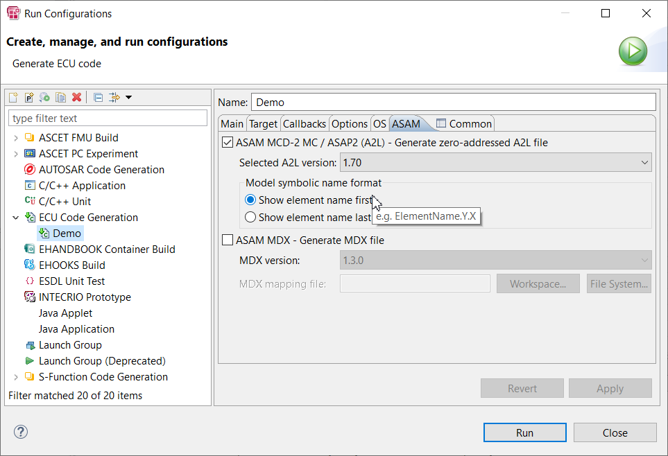
In the above JSON file, ‘elementNameFirst’ parameter corresponds to the ‘Model symbolic name format’ in the ASAM MCD section under the ‘ASAM’ tab in the launch configuration for ECU code generation in ASCET-DEVELOPER tool as shown below:
While the ‘includePackageName’ corresponds to the ‘Legacy code generation’ option in ‘Naming convention’ section under the ‘Options’ tab in the run configuration as shown below:
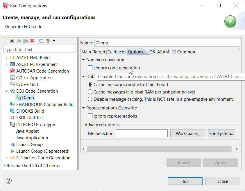
If the checkbox is selected, then ASCET Classic naming convention is used where the package names are omitted, while de-selecting it will have the package name being included in the label.
For ASCET 6
The element names could be placed first or last and their parent elements module and project names or their class instance names could be appended also.
With the JSON file shown below, models in the container will have the element name placed last and will be appended with the class instance names. This is also the default, if no label configuration is provided.
{
	"ASCET": {
		"elementNameFirst": false,
		"includeModuleName": false,
		"includeProjectName": false,
		"includeClassInstanceName": true
	}
}
For example, an instance “componentInstance” of class “Component” having a class element “signal”, placed within a module “RootModule” of project “Project” would have the name as in the below table according to the various combinations provide in JSON file. This name is used to connect to INCA on EHANDBOOK-NAVIGATOR.
| includeProjectName | includeModuleName | includeClassInstanceName | elementNameFirst | Name |
|---|---|---|---|---|
true |
true |
true |
true |
signal.componentInstance.RootModule.Project |
true |
true |
true |
false |
Project.RootModule.componentInstance.signal |
true |
true |
false |
true |
signal.RootModule.Project |
true |
true |
false |
false |
Project.RootModule.signal |
true |
false |
true |
true |
signal.componentInstance.Project |
true |
false |
true |
false |
Project.componentInstance.signal |
true |
false |
false |
true |
signal.Project |
true |
false |
false |
false |
Project.signal |
false |
true |
true |
true |
signal.componentInstance.RootModule |
false |
true |
true |
false |
RootModule.componentInstance.signal |
false |
true |
false |
true |
signal.RootModule |
false |
true |
false |
false |
RootModule.signal |
false |
false |
true |
true |
signal.componentInstance |
false |
false |
true |
false |
componentInstance.signal |
false |
false |
false |
true |
signal |
false |
false |
false |
false |
signal |
The A2L file, generated by ASCET with selected ECU target EHOOKS, has a pre-fix appended to all measurement signals and parameters. This prefix is configurable in the options dialog in ASCET:
Options -> Targets -> EHOOKS -> Name Templates: Global Namespace Prefix
With the JSON file shown below, prefix can be added to all measurement signals and parameters.
{
	"ASCET": {
		"elementNameFirst": false,
		"includeModuleName": false,
		"includeProjectName": false,
		"globalNamePrefix": "XY_"
	}
}
For Simulink
EHB-CB provides the option to add a configurable and invisible unique name to blocks, signals and buses in the Simulink model. This hidden unique name is then used for measurement, calibration and diagnostics (MCD) features like INCA connectivity in EHB-NAV.
Using the JSON file shown below, labels can be configured with unique names for Simulink signals, propagated signals, or signal objects. The configuration of unique names for signals can be achieved through a common configuration with exact or pattern-based mapping, as referenced in the Common section of the JSON file.
Example: Adding Unique Name for signals
{
	"Common": {
		"exact": {
			"Signal Name": "Replaced_Signal_Name_used_in_MCD"
		}
	}
}
With the JSON file shown below, Simulink blocks of block type "Constant" will have label configured via uniqueName.
Example: Adding Unique Name for the Constant blocks
{
	"Simulink": {
		"blockRules": [
			{
				"selectors": [
					{
						"parameter": "BlockType",
						"value": "Constant"
					}
				],
				"uniqueName": "${Value}"
			}
		]
	}
}|
JSON file path has to be given as an argument for command-line parameter "-labelconfig" |
{
	"Simulink": {
		"blockRules": [
			{
				"selectors": [
					{
						"parameter": "BlockType",
						"value": "Inport"
					}
				],
				"replacements": [
					{
						"parameter": "Name",
						"regex": "(.*)",
						"replacement": "$1__TestSuffix"
					}
				],
				"uniqueName": "Test_prefix.${Name}"
			}
		],
		"nonVirtualBusRules": [
			{
				"busNameSelector": {
					"value": "signalBus"
				},
				"busElementNameSelector": {
					"regex": "signal__(.*)"
				},
				"busNameReplacement": {
					"regex": "prefix_(.*)_suffix",
					"replacement": "$1"
				},
				"busElementNameReplacement": {
					"regex": "(.*)__(.*)",
					"replacement": "$1"
				},
				"uniqueName": "${busNameReplacement}.${busElementNameReplacement}"
			}
		]
	}
}
Configuration for blockRules
BlockRules assist to configure uniqueName for any type of Simulink blocks based on selectors and replacements configurations. It is possible to provide list of blockRules [0…n].
selectors
selectors are filters that are applied to select the block based on the provided key-value pairs.
| Key | Value | Optional |
|---|---|---|
parameter |
Valid Simulink block parameter |
No |
value |
Simulink block parameter value |
Yes |
regex |
Simulink block parameter value regex pattern |
Yes |
-
selectors are composed of either parameter and value combination or parameter and regex combination.
-
It is possible to provide list of selectors [0…n].
-
If a blockRule does not contain any selectors, then a uniqueName will be created for all the blocks.
-
To construct a uniqueName from blockRules, all the defined selectors have to be satisfied.
replacements
replacements are optional.
| Key | Value | Optional |
|---|---|---|
parameter |
Valid Simulink block parameter |
No |
regex |
Simulink block parameter value regex pattern |
No |
replacement |
Prepare an unique name using regex groups or text |
No |
|
A replacement is composed of "parameter" and "regex" applied on "parameter". |
Example:
"replacements": [
	{
		"parameter": "Name", (1)
		"regex": "(.*)", (2)
		"replacement": "$1__Suffix" (3)
	}
]| 1 | "parameter" key has the value as "Name"(which is a Simulink block name) |
| 2 | The key "regex" has a pattern which will be applied on this Simulink block name to match all the characters of this name. |
| 3 | The "replacement" key’s value will replace the matched characters with the replacement value(in the example "parameter" is appended by _Suffix ⇒ Name_Suffix) |
The resultant value after "replacement" will be used as expression in the uniqueName.
uniqueName
-
The uniqueName key is mandatory, and corresponding labels are only created if "uniqueName" is provided in the JSON configuration file.
-
uniqueName is composed of fixed expressions or text
-
uniqueName is composed of expressions, where each expression starts with "$" followed by "{" and ends with "}".
Examples for uniqueName:
$\{Sample1}_$\{Sample2}_suffix (1)| 1 | Sample1, Sample2 here are place-holders for block parameter values defined inside the model. If the replacements are provided for Sample1 or Sample2 it will replace expression using "replacement" value otherwise "block parameter" value is considered. |
Replacement results with example data: "abc", "efg"
Template for uniqueName |
Resulting uniqueName |
${Sample1}_${Sample2}_suffix |
abc_efg_suffix |
prefix_${Sample1}_${Sample2}_suffix |
prefix_abc_efg_suffix |
prefix.${Sample1}.midfix.${Sample2}.suffix |
prefix.abc.midfix.efg.suffix |
Optional configuration involving the model name
| Expression | Description |
|---|---|
${ModelName} |
Replaced with Simulink model name |
-
${ModelName} is a predefined optional expression which will be processed during Container-Build to construct the unique name.
Example:
{
	"selectors": [
		{
			"parameter": "BlockType",
			"value": "SubSystem"
		}
	],
	"uniqueName": "prefix_${ModelName}_suffix" (1)
}| 1 | If we consider ModelName as "Hello", the resulting unique name is prefix_Hello_suffix. |
Configuration for nonVirtualBusRules
nonVirtualBusRules assist to configure uniqueName for any type of Simulink buses based on "busNameSelector", "busElementNameSelector" and "busNameReplacement", "busElementNameReplacement" configurations. It is possible to provide list of nonVirtualBusRules [0…n].
-
busNameSelector is a filter, applied on the bus name, provided by value or regex configuration.
-
busElementNameSelector is a filter, applied on the bus element name (bus member), provided by value or regex configuration.
If nonVirtualBusRule does not contain any selectors, then uniqueName will be created for all the buses. To construct an uniqueName from nonVirtualBusRules, all the defined selectors are to satisfied.
-
busNameReplacement is applied on the bus name by using regex, replacement.
-
busElementNameReplacement is applied on the bus element name by using regex, replacement.
In the regex pattern, 2 fixed expressions are allowed - ${busName}, ${busElementName}. These expressions are updated before processing regex and replacement
Example:
"busElementNameReplacement": {
	"regex": "${busName}_(.*)",  (1)
	"replacement": "$1"
}| 1 | If we consider busName as "Hello", the regex is updated with Hello_(.*) |
There are four optional fixed expressions that can be used within uniqueName: ${busNameReplacement}, ${busElementNameReplacement}, ${busElementName}, and ${busName}.
{
	"busNameSelector": {
		"value": "signalBus"
	},
	"busElementNameSelector": {
		"regex": "signal__(.*)"
	},
	"busNameReplacement": {
		"regex": "prefix_(.*)_suffix",
		"replacement": "$1"
	},
	"busElementNameReplacement": {
		"regex": "(.*)__(.*)",
		"replacement": "$1"
	},
	"uniqueName": "${busNameReplacement}.${busElementNameReplacement}"
}| Expression | Description |
|---|---|
${busName} |
Replaced with bus name |
${busElementName} |
Replaced with bus member name |
${busNameReplacement} |
Replacement provided in the non-virtual bus rule |
${busElementNameReplacement} |
Replacement provided in the non-virtual bus rule |
For AUTOSAR
EHANDBOOK Container-Build provides the option to add a configurable and invisible unique name to AUTOSAR ports and its interfaces in the interface function overview. This hidden unique name is then used for MCD features like INCA connectivity in EHANDBOOK-NAVIGATOR.
{
	"AUTOSAR": {
		"includeSwcInstanceName": true,
		"includePortName": true
	}
}
In the above JSON file, ‘includeSwcInstanceName’ parameter applies the instance name of the component to be included in the name of port and interface. 'includePortName' parameter applies the port name to be added in the name of the interface.
For example, a component instance “component” containing a port "port" having an interface "interface" would have the name as in the below table according to the various combinations provide in JSON file.
includeSwcInstanceName |
includePortName |
|
true |
false |
|
true |
component.port.interface |
component.interface |
false |
port.interface |
interface |
Excluding Packages for ASCET-DEVELOPER
In the workspace of an ASCET-DEVELOPER project, block diagrams are organized by means of so-called packages. When the EHANDBOOK documentation is generated for such models, the content for certain Class Instance blocks should not be included in certain cases. Typical cases are:
-
a Class Instance is of a library type Class where details are not required to understand the meaning of the block
-
a Class Instance block contains details which are subject to know-how protection
In the corresponding interactive model, such Class Instances should then be non-expandable such that no details are exposed, and subsequently the textual documentation for the sub blocks of that Class Instance block need to be excluded from documentation as well.
Excluding packages also have s significant improvement on RAM consumption and generation time during the Container-Build.
In order to achieve this, EHANDBOOK Container-Build offers an optional command line argument -ascetdeveloperexcludepackages. The CLI argument must point to the path of a configuration file in JSON format that contains the list of ASCET-DEVELOPER packages to exclude from document generation.
{
	"packages": [
		"packageX",
		"packageA.packageB"
	]
}
See sample ExcludePackages.json in the sub folder .\examples\configuration of your EHB-CB installation directory.
In case of nested packages, fully qualified name of the package separated by “.” (DOT) needs to be provided.
Mapping signals across domain
At EHANDBOOK, it is possible to establish communication between components across domains like AUTOSAR and MSR. To visualize these connectors in the function overview of the NAVIGATOR, a mapping file is processed during the container generation.
Generate EHANDBOOK Container
To generate an EHANDBOOK Container which connects components from different domain, you have to pass the following arguments to eHandbookCB.exe
-
-i <path to input folder> specifies the sources that shall be converted.
-
-o <path to output folder> specifies where the EHANDBOOK Container shall be generated to
-
-n <name> name for the EHANDBOOK Container file that will be generated
-
-componentconnectormappingfile "<Mapping file path>" specifies the path of the mapping file
Sample Command
C:\Program Files\ETAS\EHANDBOOK-Container-Build\eHandbookCB.exe ^
-i "<path to input folder>" ^
-o "<path to output folder>" ^
-n "<name>"^
-componentconnectormappingfile "<Mapping file path>"
The mapping file is passed via command line argument "-componentconnectormappingfile".
The mapping file is expressed in .json or .csv format and contains details of connecting signals between functions of different domains.
Mapping file specification
The following listing shows an example for the syntax of the JSON mapping file.
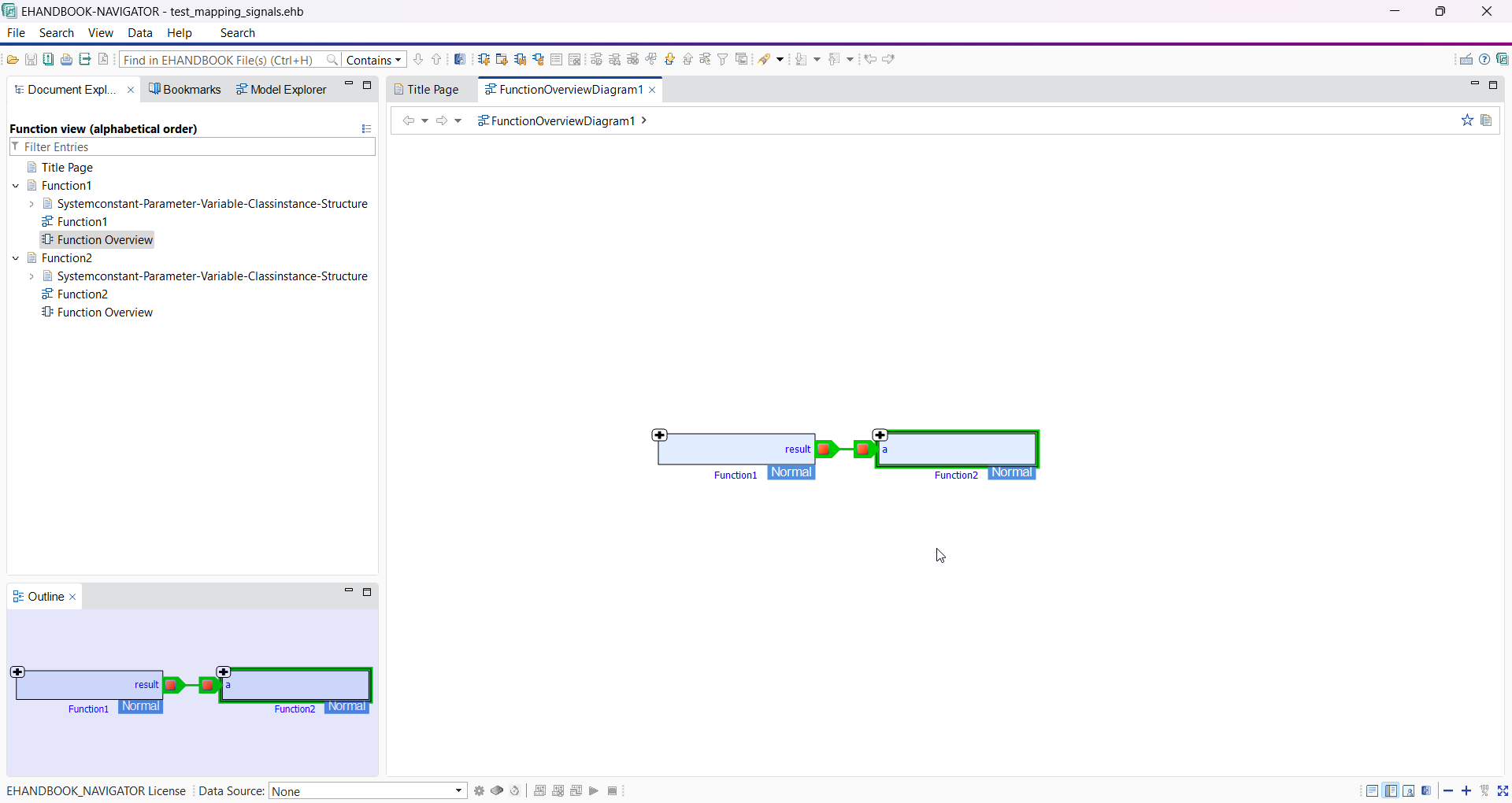
You can download the file from here.
[
	{
		"exported": {
			"port": "result",
			"component": "Function 1"
		},
		"imported": {
			"port": "a",
			"component": "Function 2"
		}
	}
]
In the above JSON file, "exported" and "imported" parameter points to the port and component details.
-
exportedPort: Name/Package path of the port which is exported from the source component.
-
exportedComponent: Name/Package path of the exporting component.
-
importedPort: Name/Package path of the port which is imported into the target component.
-
importedComponent: Name/Package path of the importing component.
The following listing shows an example for the syntax of the CSV mapping file. You can download the file from here.
| exportedPort | exportedComponent | importedPort | importedComponent |
|---|---|---|---|
result |
Function 1 |
a |
Function 2 |
Using either of the above JSON or CSV specification, functions from different domains can be connected.
Include Documentation for Nested Classes in ASCET-DEVELOPER
ASCET-DEVELOPER apps are built from a set of static entry-point classes. To re-use algorithms, these can be specified as classes and instantiated where required. When classes contain instances of other classes, this creates so-called nested classes.
Each class can be associated with some textual documentation in the form of an AsciiDoc file. Through this, the behavior of a class can be documented once.
To obtain a full documentation for a static class with EHANDBOOK Container-Build, also the textual contents associated with all instantiated and nested classes can be considered.
In order to achieve this, EHANDBOOK Container-Build offers an optional command line argument -ascetdevelopernestedclasses.
|
Depending on the usage of nested classes, this option can lead to significant increase in EHANDBOOK generation time as each class instance gets documented at the place where it is used. |
Support for Simulink Doc blocks in documentation for Simulink Addon
In Simulink Addon, the content of the Simulink doc block is extracted from the model and added as documentation (AsciiDoc) for the respective subsystem along with its screen-shot.
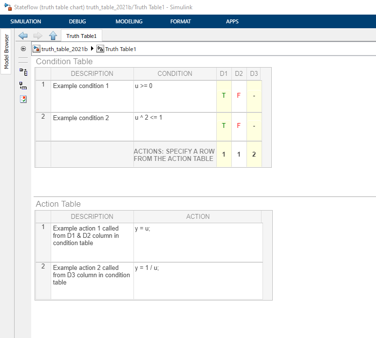
Support for Simulink truth table block in documentation
In the EHANDBOOK-NAVIGATOR when clicked on the Simulink truth block, it opens a new tab with truth tables(Condition and Action tables)
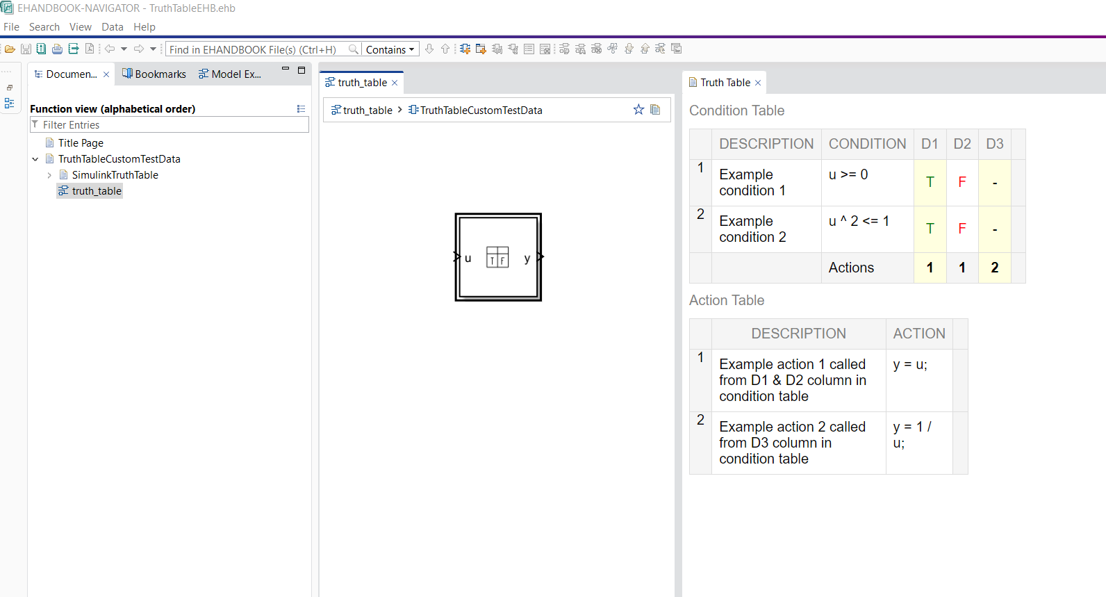
|
Local and Global search is not supported, text is selectable in EHANDBOOK-NAVIGATOR |
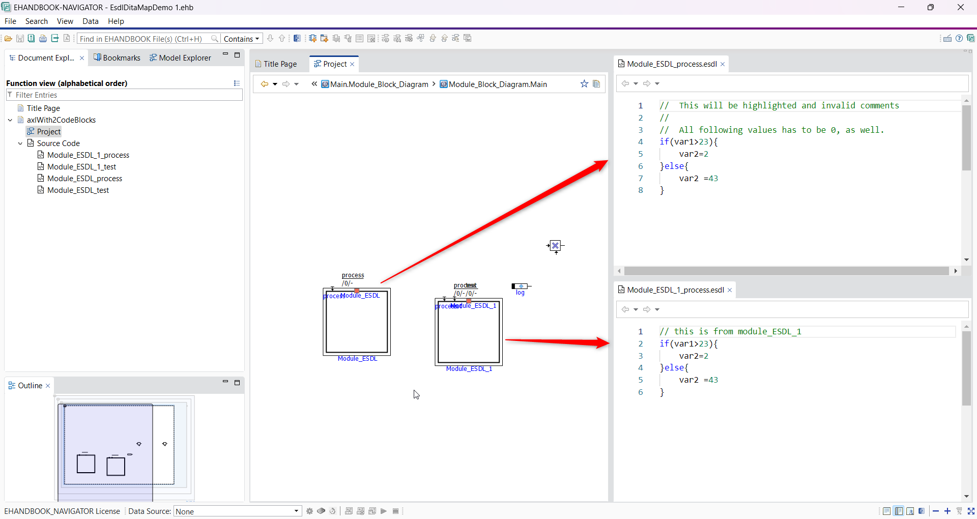
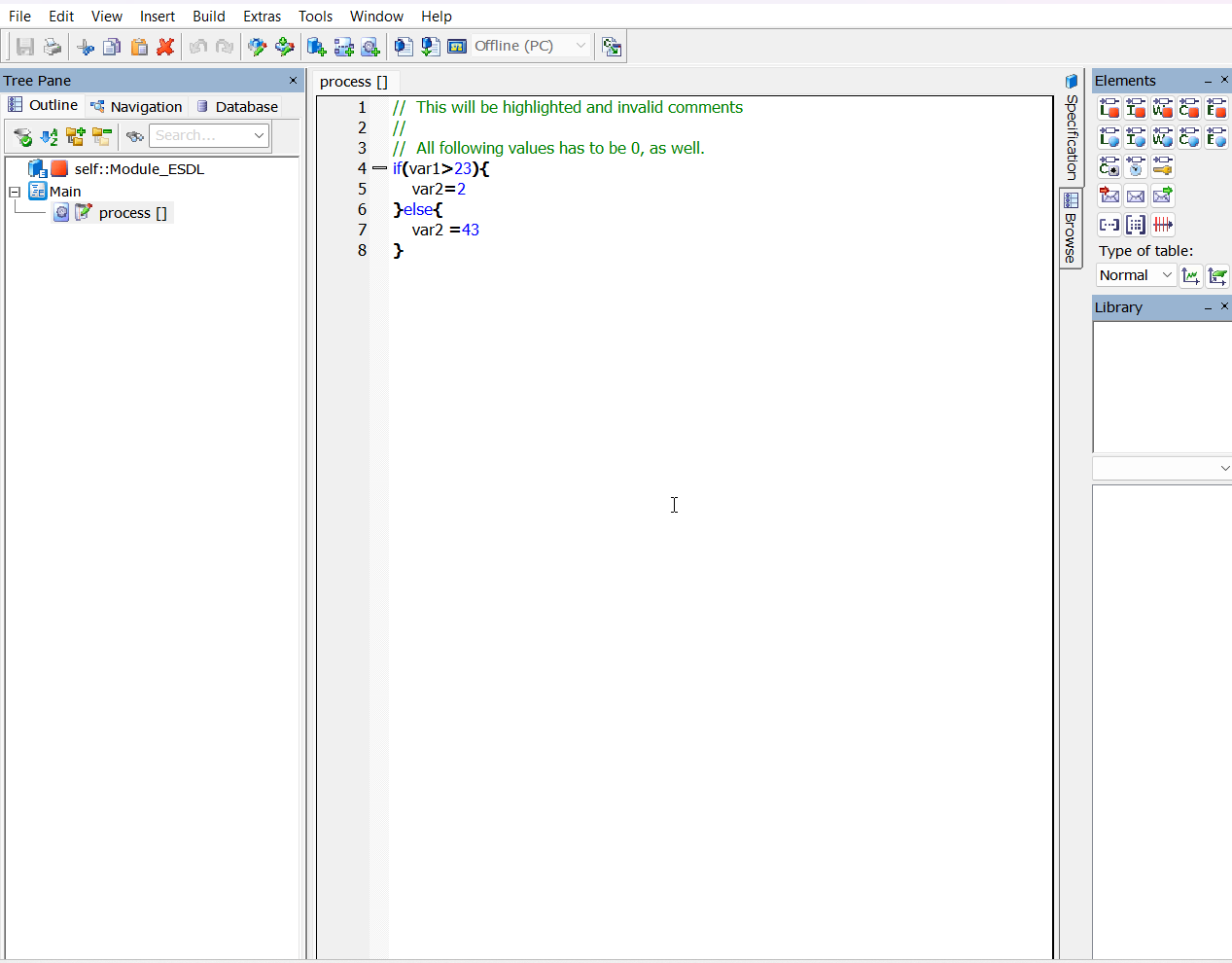
Support for ASCET module ESDL block in documentation
ESDL in ASCET is a high-level, formal language used within the ASCET environment to design and develop embedded software applications for automotive and other embedded systems. EHandbook now supports ESDL code representation through code viewer. ESDL code can be opened through model and also visible in TOC structure under Source Code. Pass command line argument -includeSourceCode to process ASCET Module ESDL blocks and to store them in the container. Additionally, local search and global search is also supported in Code Viewer.
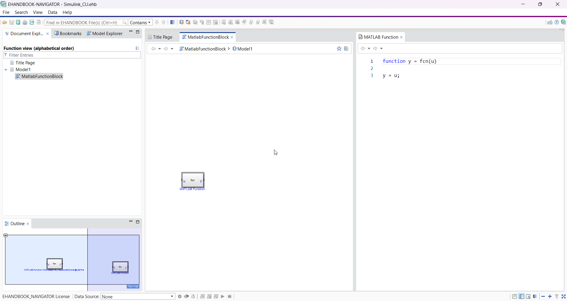
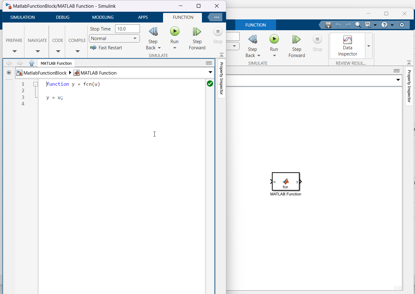
Support for Simulink Matlab Function Code block in documentation
EHandbook supports Matlab function code representation through code viewer. Matlab function code can be opened by clicking on the matlab function blocks from model viewer. Pass command line argument -includeSourceCode to process Matlab function code blocks and to store them in the container. Local search and global search is also supported in Code Viewer.
HTML Container Report
The HTML Container Report provides a structured overview of issues encountered during container generation. It helps users quickly identify errors, warnings, broken images, and affected function components.
The HTML Container Report is generated by default during container generation. The report is created in the specified output directory.
Dashboard
The Dashboard provides a high-level overview of the container generation and its health status.
It contains the following sections:
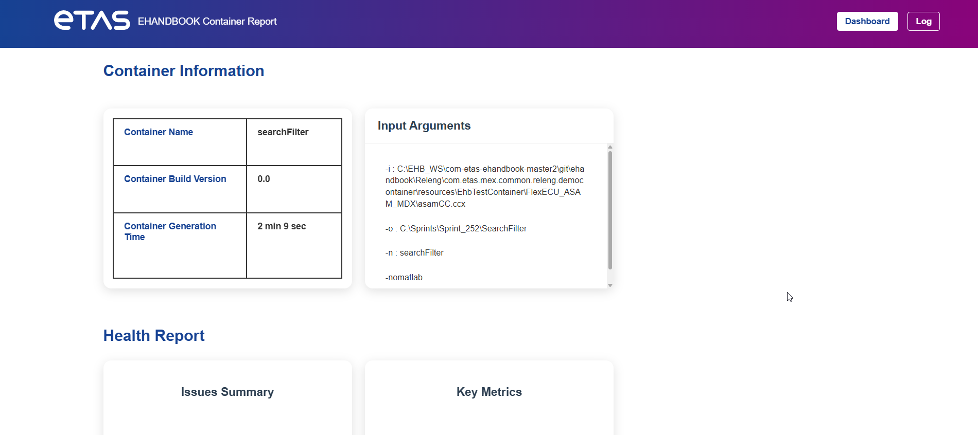
Container Information
The Container Information section displays metadata about the generated container.
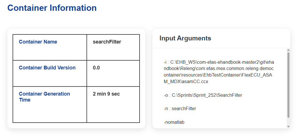
The following information is shown:
| Field | Description |
|---|---|
Container Name |
Name of the generated container. |
Container Build Version |
Version number of the generated container. |
Container Generation Time |
Total time required to generate the container. |
Input Arguments |
Command line parameters used during container generation. |
The Input Arguments section helps users to verify the exact configuration used during generation.
Example parameters include:
-
Input model path
-
Output directory
-
Container name
-
Additional arguments
Health Report
The Health Report summarizes the overall health of the generated container.
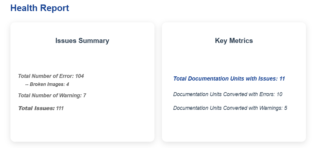
It contains two panels:
Issues Summary
The Issues Summary provides a quick overview of detected issues.
Example information displayed:
| Metric | Description |
|---|---|
Total Number of Errors |
Number of errors detected during container generation. |
Broken Images |
Images referenced in the model but not found during generation. |
Total Number of Warnings |
Warnings generated during container conversion. |
Total Issues |
Total number of detected issues including errors and warnings. |
This section helps users quickly assess the severity of problems in the container.
Key Metrics
The Key Metrics panel summarizes issues related to function components.
Example metrics include:
| Metric | Description |
|---|---|
Total Documentation Units with Issues |
Number of Documentation Units affected by errors or warnings. |
Documentation Units Converted with Errors |
Documentation Units that were converted but contain errors. |
Documentation Units Converted with Warnings |
Documentation Units converted successfully but with warnings. |
These metrics help identify problematic components in the model.
| The metrics Components Converted with Errors and Components Converted with Warnings are interactive links. Selecting one of these metrics opens the Detailed Log View and automatically filters the log entries according to the selected issue type. |
Detailed Log View
The Detailed Log View provides a complete list of all log entries generated during container creation. It allows users to analyze errors, warnings, and other issues in detail.
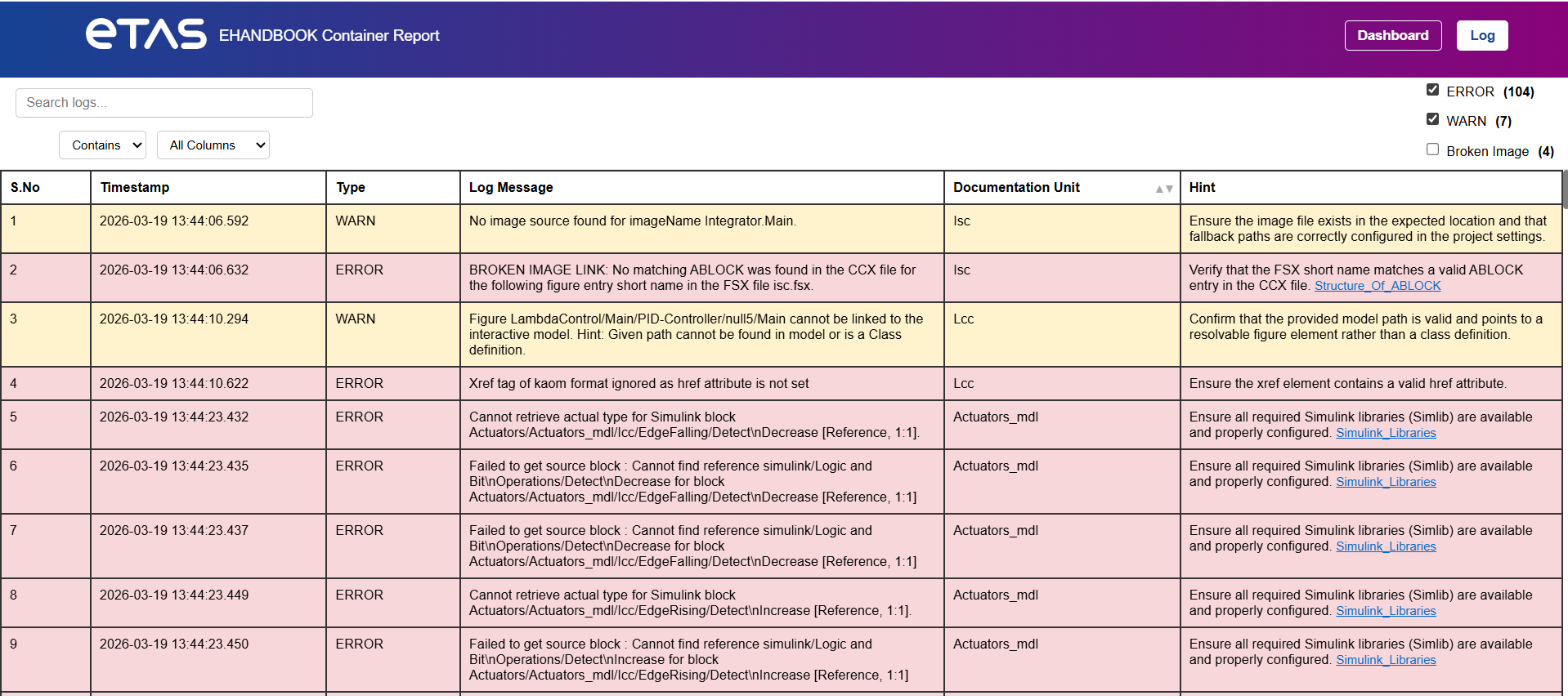
Each log entry contains the following fields:
| Column | Description |
|---|---|
S.No |
Sequential log entry number. |
Timestamp |
Time when the log entry was generated. |
Type |
Severity level of the log entry. Possible values include: * ERROR * WARN |
Log Message |
Detailed description of the issue. |
Documentation Units |
Name of the affected Documentation Units. |
Hint |
Guidance on how to resolve the issue. In some cases, the hint also contains hyperlinks to relevant EHANDBOOK documentation, enabling users to navigate directly to detailed explanations or recommended solutions. |
Severity Levels
The report categorizes log entries by severity.
| Severity | Description |
|---|---|
ERROR |
Indicates a critical issue that may affect container generation or functionality. |
WARN |
Indicates a potential problem that does not stop container generation but may affect quality. |
Search Functionality
The report provides a search feature that allows users to locate specific log entries.
Users can search by:
-
Log message
-
Documentation Units
-
Hint text
Search options include:
| Option | Description |
|---|---|
Contains |
Finds entries containing the specified text. |
Exactly |
Finds entries matching the exact search text. |
Users can also choose which column to search using the column selector.
Example:
-
Search within Log Message
-
Search within Hint
Log Filtering
Users can filter log entries by issue type.
Available filters include:
-
Errors
-
Warnings
-
Broken Images
Selecting a filter updates the table to display only the relevant log entries.
Example:
-
Show only ERROR logs
-
Show only WARN logs
-
Show only logs related to Broken Images
Typical Usage Workflow
A recommended workflow for analyzing the report:
-
Open the HTML Log Report.
-
Review the Health Report to understand the overall container status.
-
Check the Issues Summary to see the number of errors and warnings.
-
Review the Key Metrics to identify affected documentation units.
-
Navigate to the Detailed Log View.
-
Use Search or Filters to locate specific issues.
-
Follow the Hints or documentation links to resolve issues.