Tutorial: Directory-based EHB-CB for C-Code
Introduction
Welcome to EHANDBOOK! If you don’t know about EHANDBOOK yet, check out the overview at www.etas.com/ehandbook to get a background on what EHANDBOOK is, the problems it addresses and the benefits it provides.
In this tutorial, we are going to build a small EHANDBOOK Container for a single ECU function implemented by C-code using the Directory-based EHANDBOOK Container-Build tool-chain.
If you are interested in ASCET 6, ASCET-DEVELOPER or Simulink models, there are similar tutorials available as this one. Also, if you are more interested in ASAM-based XML formats for ECU software documentation, there is another EHANDBOOK Container-Build tool-chain available with a separate set of tutorials.
So let’s get started!
Installation
Prerequisites
In order to install and execute EHANDBOOK tools, you need a PC (or laptop) with Microsoft Windows 11.
You also need administrator rights to install the tools and license keys. For license keys, please contact your local ETAS sales office.
Installation of EHANDBOOK Container-Build tools
For this tutorial, we’ll use the Directory-based EHANDBOOK Container-Build tools. You can download the latest version from the ETAS Download Center.
Installation of EHANDBOOK-NAVIGATOR
To explore the generated EHB Container, you also need EHANDBOOK-NAVIGATOR installed. You can download the latest version from the ETAS Download Center.
License keys
ETAS EHANDBOOK products are protected by electonic license keys. Please ensure that you have valid license keys to operate the tools.
For trial purposes, you can obtain evaluation licenses for a limited time.
Setting up the input data
To generate EHB Containers using the Directory-based EHANDBOOK Container-Build tools, the input data such as models, interface and label descriptions as well as textual documentation must be arranged in a directory structure. The directory structure must follow a specific convention:
-
A root directory: This directory is passed to EHB-CB tool-chain as input directory
-
One or more sub-directories: Each sub-directory represents a separate function
-
Within each sub-directory, files with model data, interface and label description as well as textual description is placed
└── ECU_SW_XYZ
    ├── Function1
    │   ├── function_1_implementation.c
    │   ├── interface_and_labels.xlsx
    │   └── textual_description.adoc
    .
    .
    .
    └── Function_n
        ├── function_n_implementation.c
        ├── interface_and_labels.xlsx
        └── textual_description.adoc
Directory structure for the input data
Create a new directory EHB_CCode_Example_V1 to hold the input data for the EHB Container.
Within that directory, create a sub-directory Function 1 to hold the sources of the ECU function we want to document. The sub-directory resembles a so-called documentation unit, i.e. an entity which contains all information required to document an ECU function.
C code
We’ll start with a small function implemented in C code.
You can either create your own C code or download the C code depicted below here.
int a;
int b;

int result;

void calc() {
	result = a+b;
}
Place the C code file in the directory holding the input data the ECU function Function 1.
Your directory structure should look like this:
└── EHB_CCode_Example_V1
    └── Function 1
       └── function_implementation.c
|
Generating the first EHB Container
We’ll use the Directory-based EHANDBOOK Container-Build tool in GUI (Graphical User Interface) mode to generate the first EHANDBOOK Container for our example.
In the installation directory, double-click on the eHandbookCB.exe to launch the tool in GUI mode. Alternatively, invoke eHandbookCB.exe from the command line, but without any arguments.
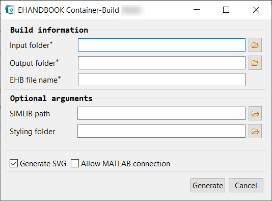
Specify the directory <path>\EHB_CCode_Example_V1 with the input data as input directory.
Then, chose a directory where you want the generated EHB Container to be placed. A good convetion is to create a directory named outputs or EHB Containers next to the directory with the inputs.
Specify EHB_CCode_Example_V1 as the name for the to be generated EHB Container.
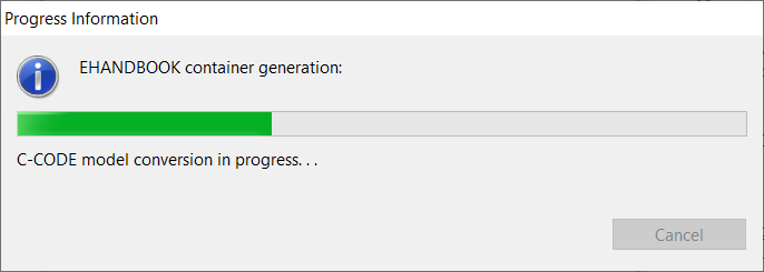
Press Generate container to start the generation.
After the generation is completed, you can either open the output directory or directly open the EHB Container.
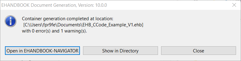
You can download the corresponding EHB Container here.
Exploring the EHB Container in EHB-NAV
Let’s open the EHB Container and inspect the example.
The EHANDBOOK Container contains exactly one ECU function - Function 1. When selecting the function in the table of contents, the chapter is empty because we have not added any textual description yet. We’ll do that later.
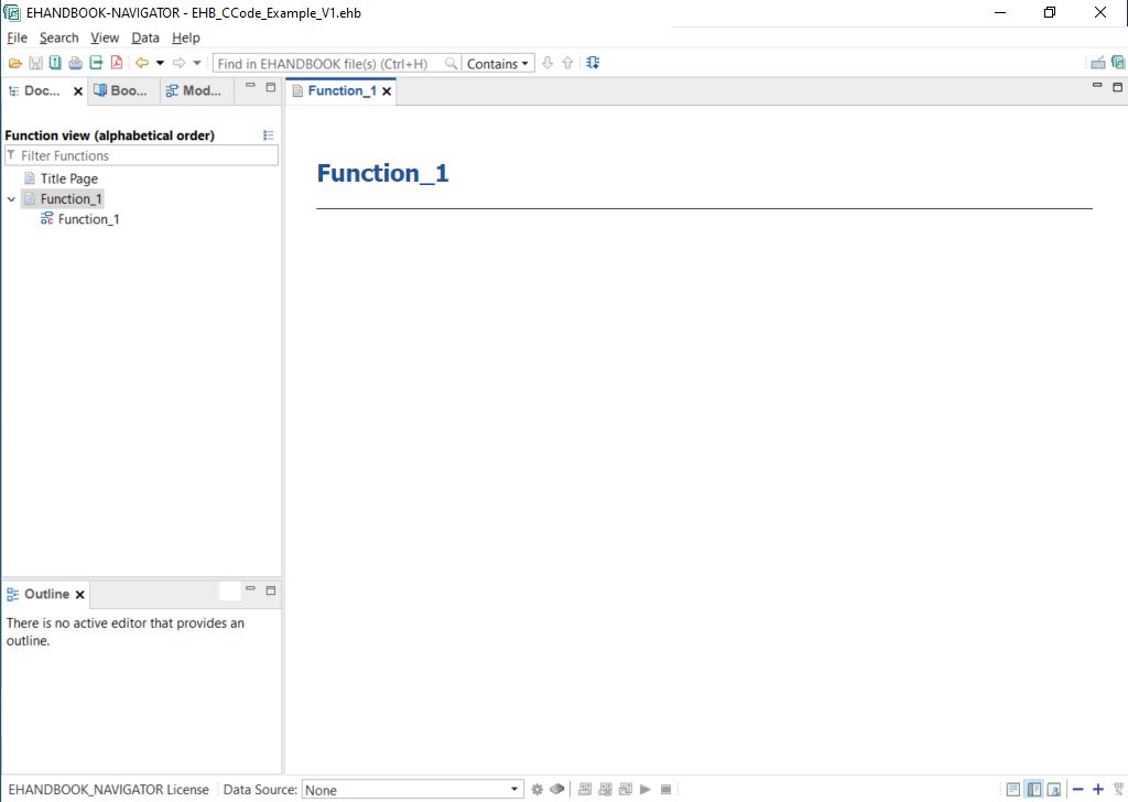
When expanding the contents of Function 1, you can see one sub-entry with a special icon:
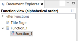
The entry links to the C-code-based interactive model.
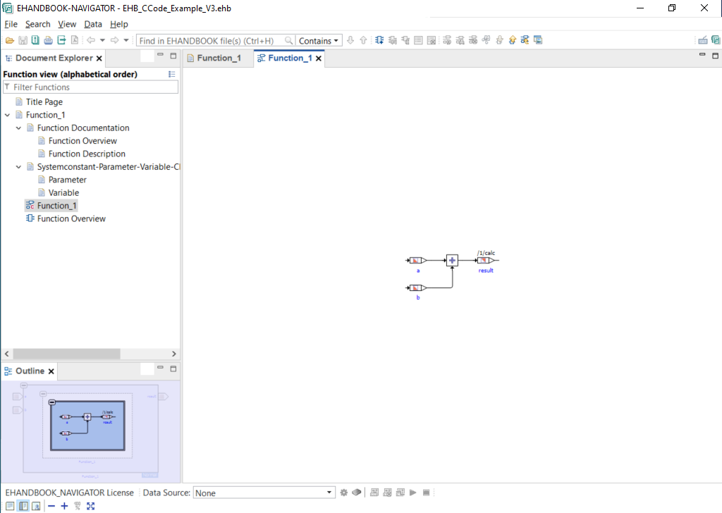
Click on the sub-entry to open the C-code-based interactive model. The model is opened in a new tab.
The C-code-based interactive model directly resembles the program structure of the C-code sources. As root-level, the set of top-level functions is shown - in this case, only one - calc.
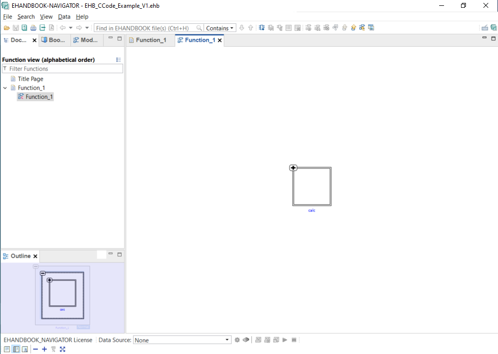
Click on the + button to expand the contents.
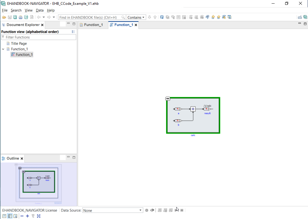
EHANDBOOK-NAVIGATOR now unfolds the contents of the function calc and embeds them in the context. The data and control flows of the algorithms contained in the C-code sources are visualized as block diagram. The diagram itself is layouted using an automatic layout algorithm.
When switching to the Model Explorer, you can inspect the hierarchies of the complete ECU function as a tree view.
Summary and next steps
Our first example is already functional, but not yet complete. It lacks two more pieces of information:
-
a textual description to describe what the ECU function does
-
an interface and label specification to denote how the ECU function connects to other ECU functions
Let’s add them in the next sections.
Adding label information and interface specifciation
In our example, the function reads two variables - a and b from global memory and writes the output to a global variable result. The global variables denote the interface of the ECU function.
To document this appropriately, EHANDBOOK offers the possibility to express this information as structured tables for variables and parameters. Furthermore, a graphical visualization can be derived by means of a function overview.
Input data for label information and interface specification
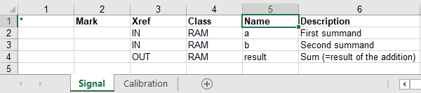
To document information about the labels used by the ECU function as well as the interface specification in the EHB Container, this has to be described in the form of an Excel file which is stored in the same directory as the C-code sources.
The Excel file template comes with two sheets: one for signals and one for calibrations.
Signals are global variables which can be measured with the help of measurement tools such as ETAS INCA. Signals which are read and written by an ECU function are used to exchange data with other ECU functions.
Calibrations are variables for which the values can be changed / fine-tuned with the help of calibration tools such as ETAS INCA. Calibrations can be e.g. single scalar values take the form of curves or maps which are interpreted by 1D or 2D interpolation routines.
For our example, create an Excel file with the following two sheets and store it in the directory where the C-code files are located.
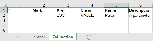
Alternatively, you can also download the filled in Excel file here.
Generating the EHANDBOOK Container
To generate the EHANDBOOK Container using the EHB-CB tool, follow the same steps as described earlier.
-
Launch the EHB-CB tool in GUI mode
-
Specify the directory with the input data as input location
-
Specify a directory as the output location
-
Start the generation
You can also download the corresponding EHB Container here.
Exploring the EHANDBOOK Container in EHB-NAV
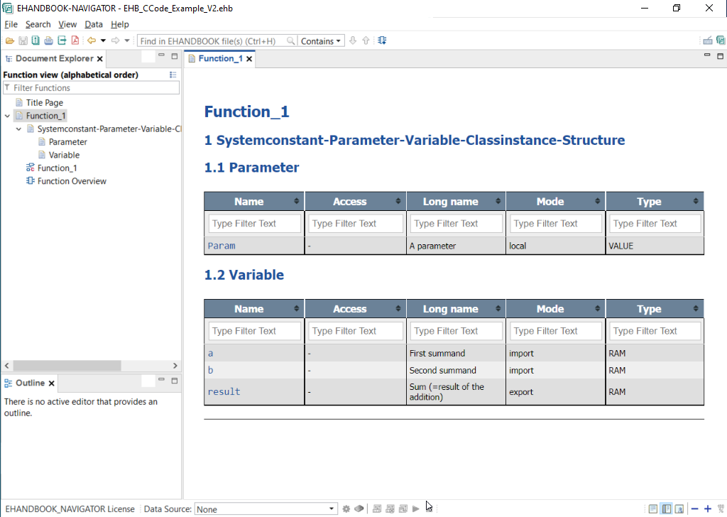
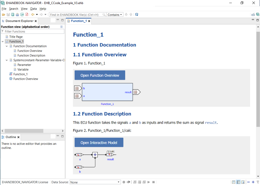
When you open the EHB Container in EHB-NAV, the first difference you will notice to the first example is that there is some textual content in the documentation for Function 1.
For signals and calibrations, EHANDBOOK Container-Build automatically generates an additional sub-section and lists the details for these labels as structured tables.
When you double-click on the entry Function Overview, a new tab is opened which shows the external interface of the ECU function as a model view.
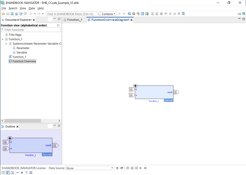
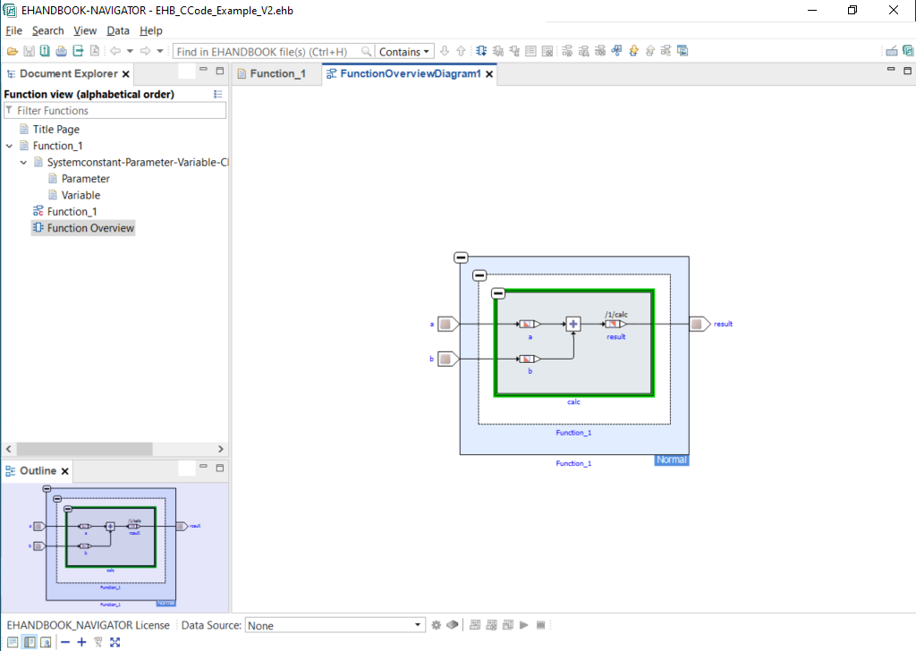
You can now start to expand the function overview block. This will expose the details of the C-Code based interactive model.
Notice that the input and output signals used by the system function_model are connected to the so-called label ports of the function overview. Through this, the ECU function can be connected to other ECU functions, establishing a seamless signal flow diagram.
Adding a textual documentation
Textual descriptions are typically used to explain the purpose of the ECU function to the reader.
Textual documentation as AsciiDoc file
To add a textual description, you have to place a document in AsciiDoc format (.adoc) in the directory of the ECU function.
You can write a new document from scratch using a text editor or IDE (e.g., Visual Studio Code) and save it as .adoc file.
EHANDBOOK supports basic features of AsciiDoc such as document structure in the form of chapters and sub-sections. You can write paragraphs, include raster images (e.g., JPEG format) and add tables.
Alternatively, you can also download an example AsciiDoc document here.
Referencing to model screenshots
In order to document ECU functions, it is often helpful to have a model screenshot followed by some textual explanation.
EHANDBOOK Container-Build can automatically generate a screenshots for block diagram visualizations derived from C-Code that can be embedded in the textual documentation.
To generate a screenshot, you have to create a model reference to the C-function you want to depict. This can be achieved with the EHANDBOOK model reference directive:
ehbmodelref::<hierarchy-path-to-c-function>[]
For example, to obtain a model screenshot for the block diagram of the calc function in the C-code source of Function_1
ehbmodelref::"Function_1/Function_1/calc"[Function_1/Function_1/calc]
Generating the EHANDBOOK Container
To generate the EHANDBOOK Container using the EHB-CB tool, follow the same steps as described earlier.
-
Launch the EHB-CB tool in GUI mode
-
Specify the directory with the input data as input location
-
Specify a directory as the output location
-
Start the generation
You can also download the corresponding EHB Container here.
Exploring the EHANDBOOK Container in EHB-NAV
When you open the EHB Container in EHB-NAV, the chapter now also contains a chapter Function_1 with sub-section Function Description.
In the section Function Description, we had given a brief textual explanation of what the ECU function does. Furthermore, we had given a reference to the subsystem Subsystem. EHANDBOOK Container-Build has generated a model screenshot and integrated this a the place of the model reference.
Furthermore, the model screenshot is linked to the interactive model. By clicking on the button Open interactive model, the block diagram for the subsystem is opened in a new model viewer tab where it can be further explored.
Organizing Shared Implementations with a Library Folder
To manage shared C or header files (e.g., common utilities or reusable logic) used by multiple functions, consider organizing them in a dedicated library folder. This folder can reside outside the main input directory and be referenced through your C project’s build configuration.
Example structure with library folder:
└── ECU_SW_XYZ
	├── Function1
		├── function_1_implementation.c
	├── Function2
		├── function_2_implementation.c
└──lib
	├── shared_util.c
	├── shared_util.h
To make the library visible to the Container-Build toolchain, specify the folder’s path in the C-code configuration file’s libraryPath setting.
Minimal C-Code Example Using a Shared Library
Let’s illustrate how to incorporate a shared library with a minimal C-code example.
lib/shared_util.h)#ifndef SHARED_UTIL_H
#define SHARED_UTIL_H
int addValues(int a, int b);
#endiflib/shared_util.c)#include "shared_util.h"
int addValues(int a, int b) {
return a + b;
}Function1/function_1_implementation.c)This function demonstrates usage of the shared_util library.
#include "shared_util.h"

int computeMotorSpeed(void) {
    int base = 100;
    int offset = 20;

    // Library function used here
    return addValues(base, offset);
}Function2/function_2_implementation.c)Similarly, this function also leverages the shared_util library.
#include "shared_util.h"

int computePower(void) {
    int voltage = 12;
    int current = 3;

    // Same library function used here
    return addValues(voltage, current);
}
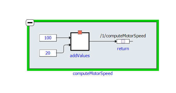
Impact of Library Configuration on EHANDBOOK Images
When the addValues() function is called without proper library configuration, the EHB-CB toolchain cannot locate its definition. Consequently, in the EHANDBOOK image, the function call remains unresolved and is visually represented as a "black box," indicating an unlinked dependency.
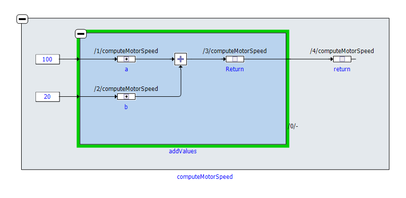
Once the library containing addValues() is correctly configured and linked, the function is fully resolved by the EHB-CB toolchain. The EHANDBOOK image then accurately displays the function within the call hierarchy, providing complete traceability and understanding of the code flow.
|
Benefits of this Library Setup
This library configuration is essential for several reasons:
|
Using a C-Code Configuration File
The C-code configuration file defines how EHANDBOOK Container-Build interprets and processes C source code during documentation generation.
Specifying the Configuration File
Provide the configuration file using the -ccodemeta command-line option with the path to your XML configuration file:
-ccodemeta "path/to/configuration.xml"
This configuration enables you to:
-
Configure shared library paths
-
Control diagram simplification
-
Enable function inlining
-
Generate hierarchical structures
Configuration File Structure
<functionmetadata:FunctionMetadataRoot
    xmlns:functionmetadata="http://www.etas.com/ehandbook/functionmetadata"
    xmlns:xmi="http://www.omg.org/XMI"
    xmi:version="2.0">

    <globalConfiguration
        libraryPath="../lib"
        inlineFunctions="true"
        simplifyDiagram="true"
        generateHierarchies="true"/>

</functionmetadata:FunctionMetadataRoot>
Configuration Parameters
| Parameter | Description |
|---|---|
libraryPath |
Specifies the directory containing external shared libraries. This enables EHB-CB to resolve functions or symbols not present in the main source files during analysis. |
inlineFunctions |
When set to |
simplifyDiagram |
Removes unnecessary nodes, unused ports, and intermediate blocks from control and data flow diagrams. This produces cleaner, more compact visualizations that are easier to read and understand. |
generateHierarchies |
Generates hierarchical diagrams instead of flat views. Functions are organized into logical levels (function → sub-function → sub-sub-function), improving navigation and comprehension of complex code structures. |
shouldReplaceReferenceArguments |
Controls how reference (pointer / by-reference) arguments are handled during inlining. When disabled (false), the inliner replaces only the additional or non-essential reference arguments that would otherwise clutter the generated model. This keeps the inlined representation clean and readable without altering semantics. |
Terminology in SWAN Debug Logs
When the -debugreq option is enabled, EHB-CB generates detailed SWAN debug logs. These logs contain technical terms that may require clarification. This section explains the key terminology you’ll encounter in the debug output.
| SWAN is a specialized library used by EHB-CB to analyze C source code, resolve dependencies, and create documentation-ready representations of code structures. |
Core SWAN Terms
| Term | Description |
|---|---|
GLOBAL_DEFS |
Global variables and functions that are defined in the available source files. SWAN collects these by analyzing all files, creating a unified dependency view, and cataloging all detected global definitions. |
GLOBAL_REFS |
Locations where global variables or functions are referenced or used within the code. |
RESOLVED_REFS |
References that successfully match an existing definition. For example, if SWAN finds a reference to variable |
UNBOUND_REFS |
Global references that cannot be matched with any available definition. These represent the remainder after resolution attempts - whatever cannot be matched becomes an unbound reference. Common causes include missing libraries, missing header files, or disabled code sections due to preprocessor directives. |
SWAN Process Messages
| Message | Description |
|---|---|
Terminating loop exception |
An informational message indicating that SWAN’s dependency resolution process has completed. SWAN iteratively searches for dependencies and matches definitions with references. When the process converges and no new information can be discovered, this message appears. This is not an error - it simply indicates successful completion of the resolution cycle. |
Missing System Constants Error |
Occurs when source code references a system constant that cannot be resolved (typically due to missing header files, configuration files, or undefined macros). During C-file analysis, this triggers a Missing System Constant message. To resolve this issue, ensure all required constants are properly declared within your project sources, as unresolved constants may cause container generation to fail for specific C-files. |
Troubleshooting Tips
-
For UNBOUND_REFS: Verify that all necessary libraries and header files are included in your project
-
For Missing System Constants: Check preprocessor definitions and ensure all required header files are accessible
-
For dependency issues: Review the complete debug log to identify missing components in your build configuration
Summary
Congratulations! The example EHB Container is now complete.
The EHB Container includes a textual documentation with automatically generated model screenshot.
Furthermore, the labels of the ECU function are documented by means of structured tables. For the interface, an automatic generated function overview is available. The latter is directly linked to the interactive model which has been generated from the Simulink model.
Here are few things you can do now:
-
Create more EHB Containers with different models. You can load and combine them in EHANDBOOK-NAVIGATOR.
-
Create a single EHANDBOOK Container with multiple functions. For this, create sibling directories next to the directory for your one ECU function, add your input data and run EHB-CB.
-
Generate a PDF documentation for the contents of your EHANDBOOK Container. Check the command-line option
-pdf. -
Apply custom styling and branding to your EHANDBOOK Container.