Using Interactive Models
The following operations explained in this section can be performed on interactive models.
Opening an Interactive Model
-
Open interactive model link
-
Tooltip
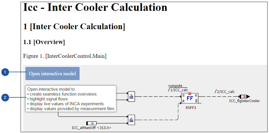
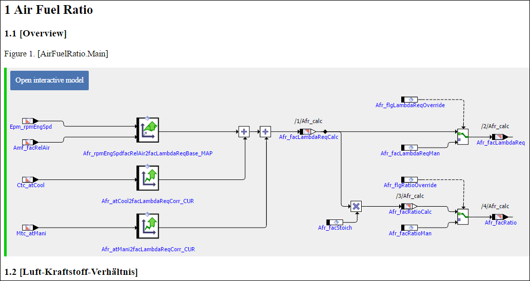
Interactive models are function models containing dynamic information. The
Model Viewer allows dynamic exploration and interaction with the interactive
model. An EHANDBOOK container having interactive models which can be opened
for interacting and exploring with the interactive models. When you hover the
mouse over Open interactive model (1), tooltip (2) is displayed.
|
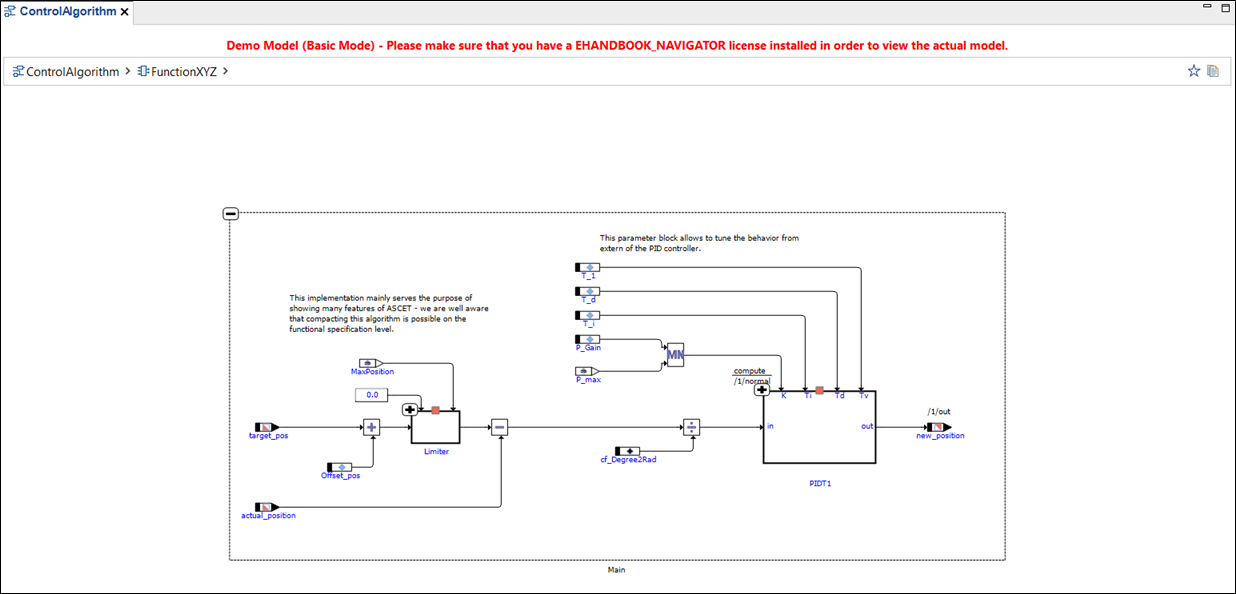
If you are using EHANDBOOK-NAVIGATOR in Basic Mode, then a dummy Interactive Model is displayed. The same dummy Interactive Model is displayed whenever you try to access an Interactive Model in Basic Mode. The functionalities of Interactive Model can be performed on the dummy interactive model available in Basic Mode. |
To open an interactive model:
-
Click Open interactive model (1) in the Document Viewer.
<Or> -
Click on the entry in the Document Explorer that refers to the model.
Applying Layouts to Interactive Model

-
Default layout
-
Auto layout
An interactive model must be open in the Model Viewer for the layout icons in the toolbar, and the Model Viewer menu in the menu bar to be visible. Two types of model layouts are provided in the Model Viewer.
-
Default Layout
-
Auto Layout
|
If you are using EHANDBOOK-NAVIGATOR in Basic Mode, only a dummy interactive model is available for applying layouts. |
To apply the default layout to the interactive model:
-
Click
Default Layout(1) in the toolbar
<Or> -
In the
Model Viewermenu, select Default Layout.
To apply auto layout to the interactive model:
-
Click
Auto Layout(2) in the toolbar
<Or> -
In the
Model Viewermenu, select Auto Layout.
NOTICE
The graphical model presentation might differ from the real ECU functionality.
The EHANDBOOK-NAVIGATOR then may contain erroneous elements and missing
user comments in an interactive model when displaying automatic layouts!
Therefore, always compare the content of the interactive model in the
EHANDBOOK-NAVIGATOR with the real ECUs function by validating that the
graphical model presentation corresponds to the ECU documentation source
before you start working.
To identify the cause for the wrong, missing or incomplete content, the producer
of the container must check the source files from where the container
was created. If the source files are correct and the appearance of the error is
reproducible, the producer of the container must contact the local sales representative
or the ETAS support to report this error.
Expanding or Collapsing Hierarchy Levels
-
Collapse
-
Expand
EHANDBOOK-NAVIGATOR supports expanding/collapsing of hierarchy levels within ASCET block diagram models and Simulink models. Expandable blocks within ASCET block diagram models are logical hierarchies and instances of ASCET classes, modules, and projects containing a block diagram specification.
To expand/collapse hierarchy levels:
-
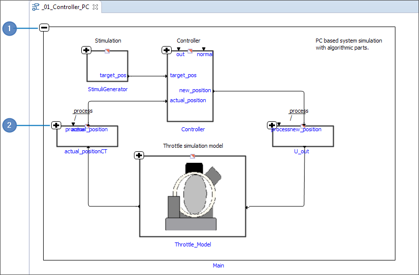
Select any hierarchical block in the model.
A '+' symbol (2) is present on the top left corner for expandable blocks, and a '-' symbol (1) is present for collapsible blocks. -
Click the '+' symbol to expand the block or click '-' symbol to collapse the expanded blocks.
|
If you are using EHANDBOOK-NAVIGATOR in Basic Mode, only a dummy interactive model is available for expanding/collapsing of hierarchy levels. |
NOTICE
The highlighted signal path in ASCET or Simulink based interactive models may be incomplete and do not correspond to the real ECUs signal path. The 'highlight Signal Flow' function analyzes how the blocks shown in the interactive model are connected by directed edges. Blocks that are interconnected via directed edges are highlighted as a result of the analysis. Note that the 'highlight Signal Flow' function only is an aid to understanding. Therefore, always compare the highlighted signal path in the EHANDBOOKNAVIGATOR with the real ECUs function by validating that the interactive model corresponds to the ECU software before you start working.
NOTICE
The highlighted signal path from C-Code based analysis in interactive models may be incomplete and do not correspond to the real ECUs signal path! The 'highlight Signal Flow' function analyzes the dependencies in C-code based interactive models. Blocks that are interconnected are highlighted as a result of the analysis. Note that the 'highlight Signal Flow' function only is an aid to understanding. Therefore, always compare the highlighted signal path in the EHANDBOOKNAVIGATOR with the real ECUs function by validating that the interactive model corresponds to the ECU software before you start working.
Function Documentation
While exploring Interactive models, there might be a need to look at the corresponding
documentation. EHANDBOOK-NAVIGATOR allows you to view the corresponding
documentation in the Document Viewer. This is possible for ASCET
block diagram models, Simulink models, C-Code derived model and it works
across the hierarchy levels as well.
To view the Function documentation:
-
Right-click on a model.
<Or> -
Select any block diagram or model in the model and right-click.
A context menu is displayed. -
Click
Show documentation.
-
A model
-
A Context menu
-
Show documentation feature
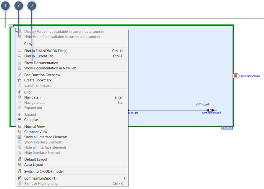
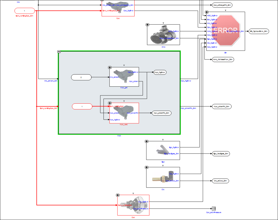
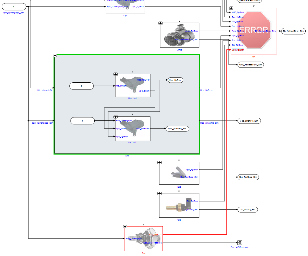
Function documentation is opened for the selected model and it is highlighted in green as shown in the image below:
|
If the corresponding function documentation is available, then Show documentation feature is enabled. Otherwise, it is disabled. |
Highlighting to Source or Highlighting to Destination
Highlight to Source and Highlight to Destination features in EHANDBOOK are
useful in large Simulink block diagrams to trace the signal path very quickly. It
uses the buses to highlight to its source or destination block(s).
To Highlight to Destination:
-
Right-click on an output block in a Simulink model.
A context menu displays. -
Select
Highlight to Destinationand the output port in the sub-menu.
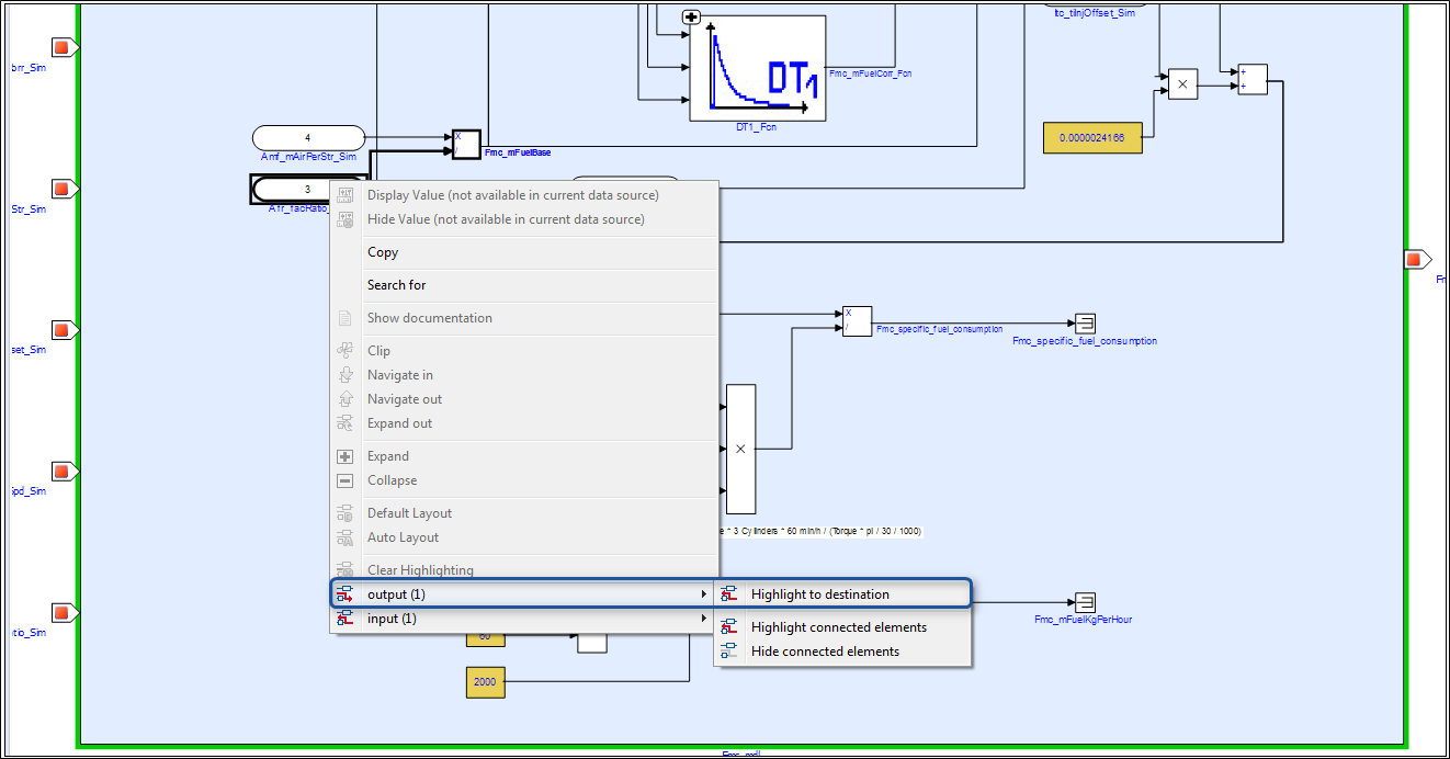
The selected port is highlighted with its signal flow.
To Highlight to Source:
-
Right-click on an output block in a Simulink model.
A context menu displays. -
Select
Highlight to Source.and the input port in the sub-menu.
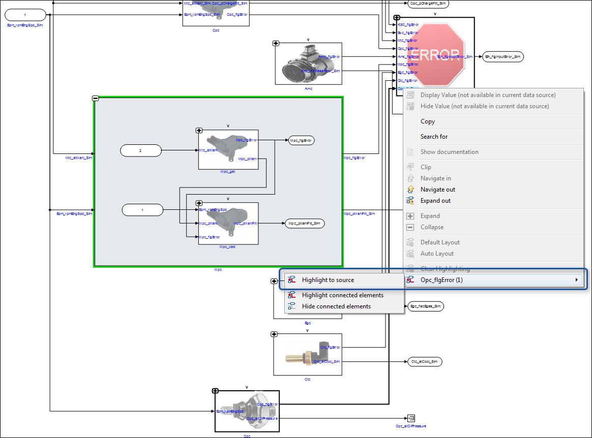
The selected port is highlighted with its signal flow.
The tracing of the signal path stops where the unknown blocks such as state flow, merge block, etc are found.
|
You can remove the highlighted signal flow with the |
|
Sub-menu for Highlight to Source/Destination will only appear when there are more than one input/output ports |
Navigation Between Hierarchy Model and Model Image
The ClickPic feature provides the possibility for you to navigate easily within the
ECU software documentation with the help of interlinked graphics that can be
clicked. On seeing an embedded hierarchy in the image of an ASCET or Simulink
model, you can navigate to where the hierarchy is documented by clicking on the
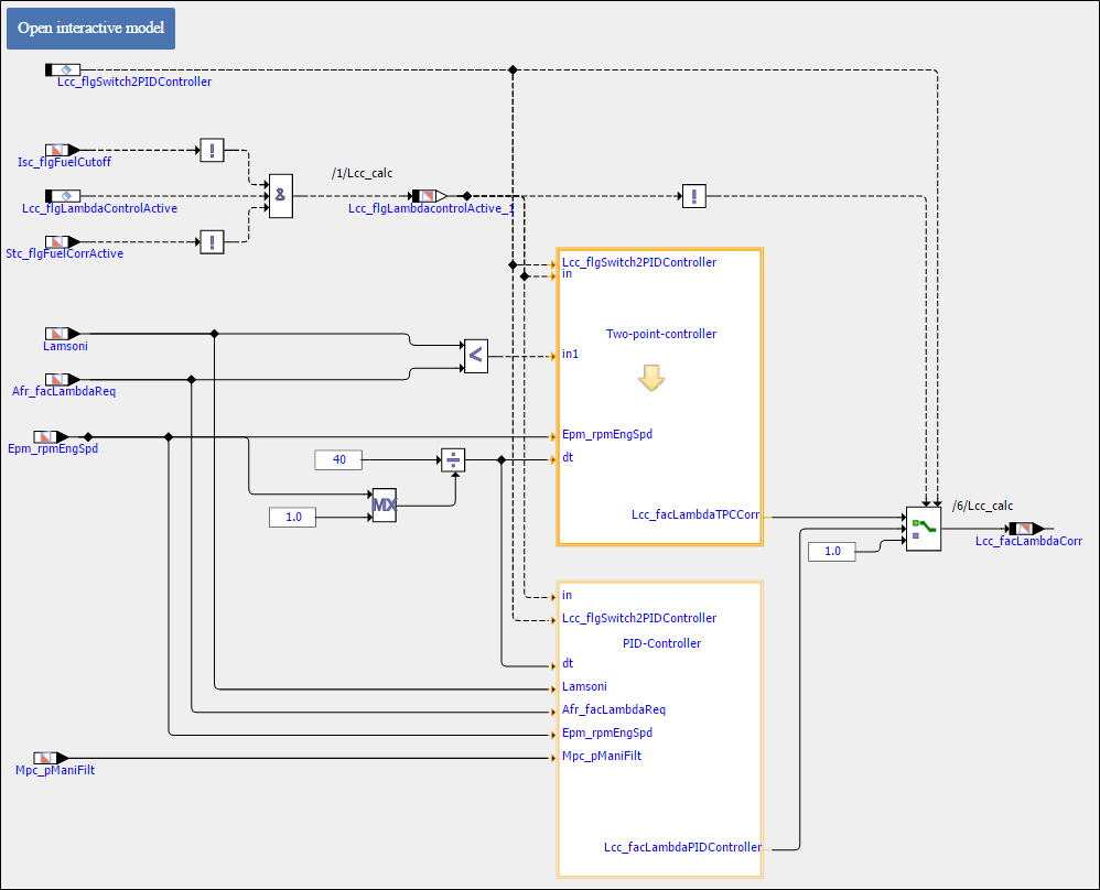
corresponding area. If a hierarchy block/class instance block is highlighted with
orange , it means that ClickPic feature is enabled for that particular block.
|
|
To navigate to the model image:
-
When you hover the mouse over the hierarchy model which is highlighted with orange, then cursor changes to a down arrow (
 ) as shown in the
image below.
) as shown in the
image below. -
Click to navigate to the model image for the hierarchy model.
A model image is displayed.
ClickPic also allows you to navigate back from model image to its parent hierarchy
model.
To navigate back to the parent hierarchy model:
-
Hover the mouse over the gray background area in a model image.
An up arrow appears ( ).
). -
Click to navigate back to its parent hierarchy model.
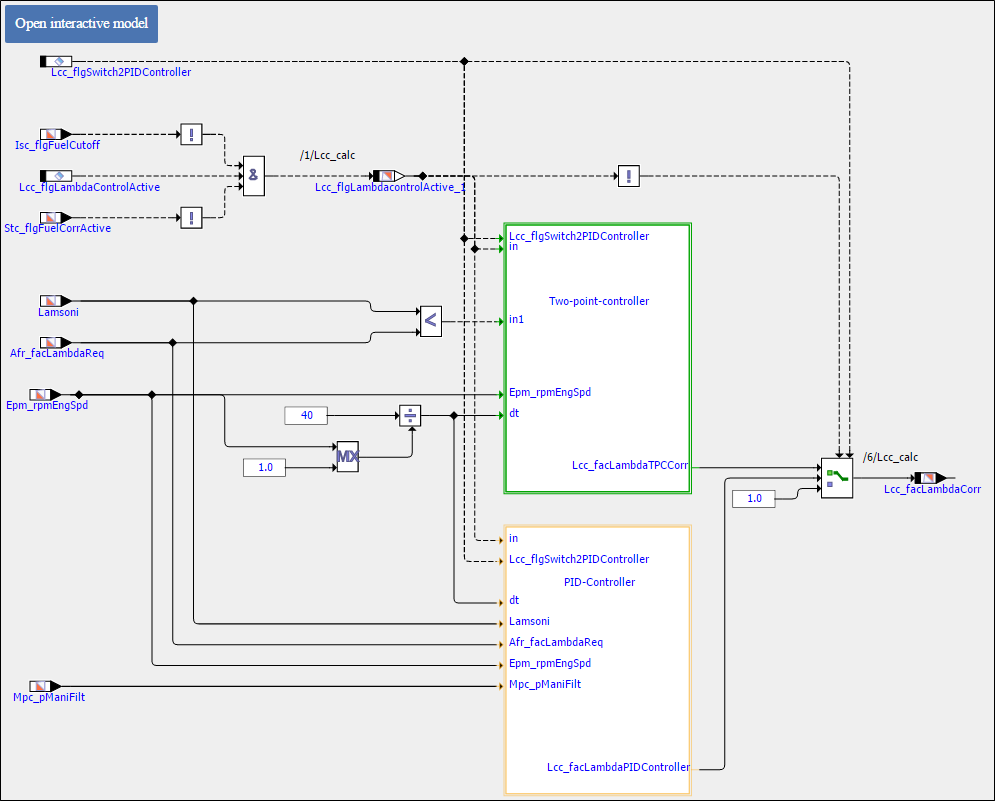
Parent hierarchy model is displayed which is highlighted with green.
|
If the corresponding parent hierarchy model is available for a model image, then only the up arrow appears to navigate back. |
Exporting as Image
The Export as Image… feature in the toolbar helps to export/save the selected
model or the function overview diagram as an image.

-
Export as Image
Follow the steps below to export as an image:
-
Open a model or a function overview diagram.
-
Click
Export as Image…on the toolbar.
Windows explorer is displayed.
<Or> -
Right-click on the interactive model or model block and select
Export as Image…in the context menu displayed. -
Specify the file name and path to save it. The image can be saved as .png/.jpeg/.bmp formats.