Simulink View Concept
The Mathworks provides a customized Simulink add-on which allows the configuration of the visual appearance of a Simulink model.
There are three so-called views defined, named EXTERNAL, INTERNAL and DETAILED. For each view, the function or software developer can define the visual appearance of Simulink blocks and subsystems.
The main purpose of the View add-on is to protect the intellectual property (IP) of the Simulink model.
The following views can be applied on Simulink elements:
-
As Line: Blocks with one input and one output are shown as a single line.
-
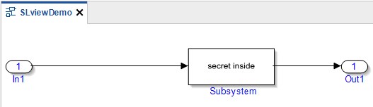
Hide Contents: Subsystems can not be opened. Inner details are hidden.
-
Invisible: Annotations / unconnected blocks are not shown.
If this customized Simulink View add-on is installed an additional menu entry is available:
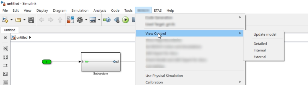
In the context menu, for each and every Simulink block its visual appearance can be configured for each view:
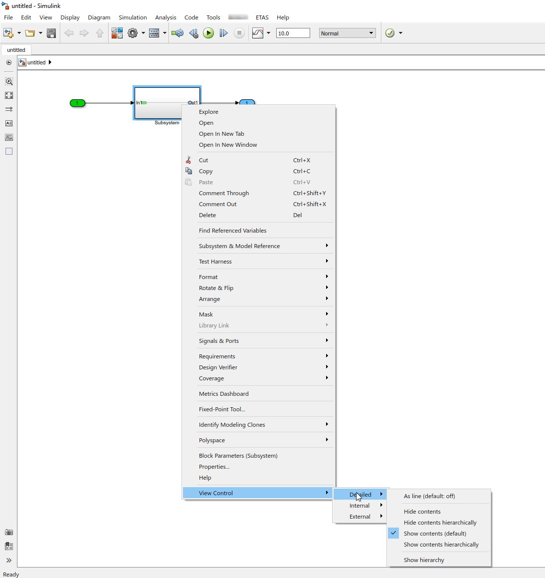
When some of these methods are used for e.g. external view, not all details of the model are shown anymore.
|
This functionality is not part of the standard Mathworks product. Mathworks will provide this feature on demand. |
|
In ETAS ASCET 6, this functionality is part of the standard product. |
Technical Realization
The Simulink View add-on creates a new sub folder below the model file. The folder has the name of the Simulink model appended with the suffix _VCFDB.
For each element of the model, the sub folder contains an XML-file which defines the visual appearance of it for every view. The name of the file must be modelName_COL_<IdNumber>.XML.
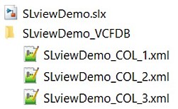
An XML-file is only required for blocks where a view should be applied.
The XML structure must follow this schema:
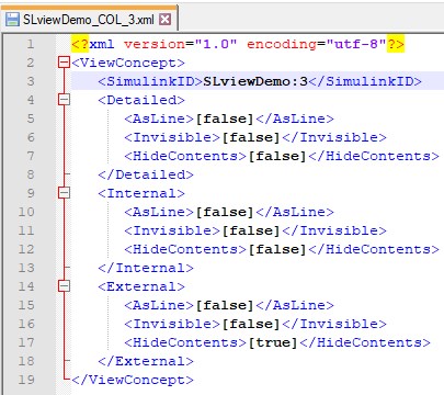
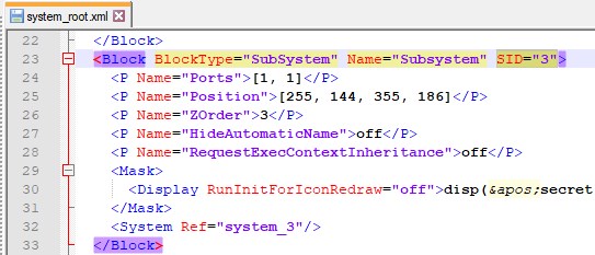
The number in the <SimulinkID> above in the XML is the ID which are defined as SIDs in the blockdiagram.XML file for every Simulink block. This file is part of the zipped Simulink model .slx file. In newer MATLAB versions, the SIDs are located in the systems\system_x.XML inside the zipped .slx file.
You can use this view concept also without the Simulink View add-on.
In this case, you have to create the files by your own manually or by a script:
-
Identify the SID of the block, for which a view should be applied
-
Create an XML-file with the view configuration for it according to the sample above
-
Store this file with the name modelName_COL_<SID>.XML in the sub folder modelName_VCFDB of your .slx model file.
Support in EHB-CB and UGG
Besides for ASCET models, the Directory-based EHB-CB and UGG are supporting this Simulink view concept in addition.
|
The ASAM based EHB-CB is supporting the Simulink view concept on special request only. To define the view for the container, the entry <SD GID="view">EXTERNAL</SD> in the CCX file must be used. This entry has then priority to the command line parameter -viewtype . |
The following steps are required that EHB takes care of the defined views in a Simulink model:
-
Make sure, that the sub folder ModelName_VCFDB with the corresponding XML-files is available below the file ModelName.slx
-
Start EHB-CB / UGG with the additional command line parameter -viewtype "EXTERNAL", "INTERNAL" or "DETAILED"
During model conversion, EHB-CB interprets the XML-files and creates model screenshots and interactive models for this particular view provided by the command line.
|
The provided view type is applied to all Simulink models of the container. All hidden elements are deleted from the interactive model before it is taken into the EHANDBOOK container. |
|
If a model hierarchy is described with text and model screenshot in |
|
If "Hide contents" is applied for a block, signal highlighting over blocks is not possible in EHANDBOOK-NAVIGATOR because the inner details are not known. |
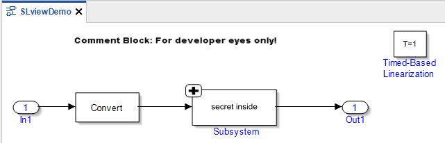
The following shows an example model where all blocks are visible. This is typically the DETAILED or INTERNAL view.
Interactive model generated with -viewtype "INTERNAL"
With the help of the Simulink View add-on, an EXTERNAL view was defined where several elements shall be hidden:
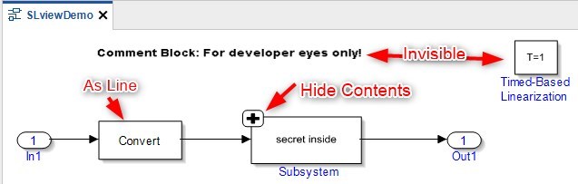
The following screenshot shows the same model in EHANDBOOK-NAVIGATOR when generated with -viewtype "EXTERNAL"