ASAM-EX Format Specification
EHANDBOOK and ASAM EX in general
The new ETAS EHANDBOOK solution is an interactive documentation tool set, making ECU software understandable. This solution consists in 3 parts: the EHANDBOOK Container-Build tool chain for the container generation, later called EHB-CB, the container itself, which is containing the documentation data in a special format and the EHANDBOOK-NAVIGATOR, the tool to work with the containers, later called EHB-NAV.
One possibility as input for EHB-CB are files in ASAM exchange format. This document describes the required structure of the ASAM files for EHB related use cases only.
For the general format and structure information of ASAM Exchange, please refer to www.asam.net. Here you can get the full specifications for -
-
ASAM CC (Container Catalog) is used for describing engineering objects:
Definition of an XML-based format for describing engineering objects such as source code, compiled objects or documentation files, and associated meta information about the objects, such as creator, name or version. Primarily used for exchanging information between OEM and supplier. -
ASAM FSX (Functional Specification Exchange Format) describes the functional behavior of software:
Definition of an XML-based format for describing the functional specification of software, primarily for the purpose of generating technical documentation. The format allows documentation via prose text in multiple languages, cross-referencing, linking and mentioning of requirements. Variations of the specification can be expressed. Is complementary to MDX, which contains the interface definitions of functions. FSX is a subset of MSRSW components -
ASAM MDX (Model Data Exchange Format) describes the software architecture and data definition of the software: Definition of an XML-based format for describing interfaces of functions, their data (variables and calibration parameters) and scheduling in ECU software. This allows the integration of such functions as object code into the overall ECU software without having access to the source code. Standard is complementary to FSX, which contains the functional description of functions. MDX is the predecessor of the AUTOSAR Software Component Template
If you have your input files in a different format, we are happy to support you with our ETAS engineering services and adapt the EHB-CB to your needs.
Here a brief overview about the ASAM concept in principle in the context of EHB:
Important Notices
NOTICE
Incomplete container content due to wrong or corrupt file formats
Content of the generated EHANDBOOK Container may be incomplete, if the input data used for generating the container are not compliant to the following file formats:
-
ASAM formats
-
CCX
-
FSX
-
MDX
-
-
Image formats
-
JPG
-
PNG
-
EPS
-
-
Formulas
-
TeX
-
-
Text formats
-
AsciiDoc (supported subset)
-
These container contents can not be displayed in the EHANDBOOK-NAVIGATOR. Therefore, always check the log file of the EHANDBOOK Container-Build, after generating a new container. Missing, incorrect or false content will be tracked in the log file.
After generating a new container:
-
Check the entries in the log file of the EHANDBOOK Container
Build indicating missing or incorrect container content.
-
Ensure that the data used during the import match the above specified formats.
-
Generate a new container.
-
Only provide containers for further usage in the EHANDBOOK- NAVIGATOR, if the log file contains no entries indicating any missing or incorrect content.
If it is not possible to completely clean up the log file, inform the intended user of the container about this missing, incorrect or false container content.
NOTICE
Incomplete container content due to defective or inconsistent input data
Content of the generated EHANDBOOK Container may be missing, if the input data used for generating the container is defective or inconsistent. Affected container contents cannot be displayed or will be displayed incorrectly in the EHANDBOOK-NAVIGATOR. Therefore, always check the log file of the EHANDBOOK Container-Build. Defective or inconsistent input data that have led to errors when converting will be tracked in the log file.
The content consistency is in the responsibility of the data supplier (documentation publisher). We recommend that the data supplier develop a standard procedure for pre-processing the input data outside the EHANDBOOK Container-Build tool chain to ensure the data consistency and to reduce the workload for reviewing the input data. In addition, the pre-processing should be properly documented to ensure transparency.
After generating a new container:
-
Check the entries in the log file of the EHANDBOOK Container-Build indicating defective or inconsistent input data.
-
If necessary, fix the incorrect or inconsistent input data.
-
Re-build the EHANDBOOK Container.
-
Only provide containers for further usage in the EHANDBOOK-NAVIGATOR, if the log file contains no entries, indicating any defective or inconsistent input data.
The ASAM Formats in particular
In principle, there are 3 different type of files, CCX, MDX and FSX. Per project, there is exactly on CCX file and typically per function one MDX and FSX file.
In the context of EHB, the CCX contains the table(s) of contents, all FCs with their references to FSX&MDX and the model locations. The FSX contains the text chapters with their texts and graphics and the MDX contains all label definitions and interfaces.
Component naming conventions for EHANDBOOK:
-
FC = function component, smallest software unit, which contains one Simulink or ASCET model
-
BC = base component, which contains multiple FCs
-
GC = group component, which contains multiple BCs
BCs and GCs allowing to design a hierarchical structure of the components, which is later on seen in the table of contents in NAV.
Supported ASAM Versions
EHB-CB supports ASAM CC in V3.0.0, ASAM FSX in V1.1.0 and ASAM MDX in V1.3.0. in their corresponding DTD versions. The supported encoding file format is UTF-8.
The keywords and objects of ASAM were read according to the standard, but interpreted to the needs of EHB. The support is limited to the use cases relevant to EHB and restricted to basic functionalities only.
The CCX File Structure
The CCX file structure for EHANDBOOK consists of a chain list of ABLOCKs, which refer other ABLOCKs using the AREF tag ID-REF value: <AREF ID-REF=”uniqueID-No”/>.
These ABLOCKs can be broadly classified and understood as Root ABLOCK, TOC ABLOCK, Components ABLOCKs (GC, BC, FC) and leaf ABLOCK (which is not having further reference to another ABLOCK)
Catalog and Root ABLOCK Usage
The CCX file starts with the CATALOG entry and a root block:
<CATALOG F-CM-TOOL-ID="$Id: catalog_V3_0_0.sl.dtd,v 1.1">
	<SHORT-NAME />
	<AREF ID-REF="EHB_Container" />
	<ABLOCKS>
		<ABLOCK ID="EHB_Container">
	...
The catalog entry has an AREF tag, which refers to the root ABLOCK.
Root ABLOCK
Referred from: <CATALOG> block with <AREF ID-REF="EHB_Container"/>
Refers to: TOC ABLOCKs/Special ABLOCKs
The Root ABLOCK provides info for the title page in EHB and refers the TOC ABLOCKS. Besides references to the TOCs, there are also some special general references to the following elements possible:
-
Global MDX file (see chapter One global MDX File)
-
Global CDF file (see chapter CDF ABLOCK Usage)
-
ASCET Library (see chapter ASCET Model Reference to global Library and other Sub-Components)
The Title Page and Project Information
The root ABLOCK contains the information about the project creation date, language, short-name, long-name, variant, etc. inside SDG tag which are used to create the title page for the container.
<!-- Root ABLOCK -->
<ABLOCK ID="EHB_Container">
	<SHORT-NAME>ehbContainer</SHORT-NAME>
	<DESC />
	<SDGS>
		<SDG GID="global">
			<SD GID="view">Detailed</SD>
			<SD GID="project_class">PVER</SD>
			<SD GID="project_longname">FlexECU-G1 Turbo</SD>
			<SD GID="project_shortname">EHB_Demo_Container</SD>
			<SD GID="project_date">2019-07-31 10:39:00</SD>
			<SD GID="Project_variant">V7.1.1</SD>
			<SD GID="Project_revision">3</SD>
			<SD GID="info_pver">EHANDBOOK Demo</SD>
			<SD GID="doc_class">SWCALDOC</SD>
			<SD GID="language">DE</SD>
			<SD GID="hide_component">true</SD>
			<SD GID="condition">true</SD>
			<SD GID="confidential_level_2">false</SD>
			<SD GID="doctype_text">Software Documentation</SD>
			<SD GID="legal_note">This document contains confidential information. Disclosure is prohibited without the written consent of ETAS GmbH.</SD>
			<SD GID="MATLAB_LIB_PATH">C:\Simulink\M160</SD>
		</SDG>
	</SDGS>
</ABLOCK>
The tag <SD GID="MATLAB_LIB_PATH"> is used to include global library files for Simulink models. For details, see chapter Simulink Model Reference to external Library.
|
The title page, the general font styling, the company logo and the footer text are configurable in the separate CSS and branding.properties files. Please refer to the document Title Page Style Guide for EHB-CB. |
Reference to TOCs
The different tables of content (TOCs), defined in separate ABLOCKS, are referenced also in the root ABLOCK.
<!-- Root ABLOCK -->
<ABLOCK ID="EHB_Container">
	<SHORT-NAME>ehbContainer</SHORT-NAME>
	<DESC />
	<AREFS>
		<AREF ID-REF="ID_00000">fcAlpha_axl</AREF>
		<AREF ID-REF="ID_00002">fcAlpha_mdl</AREF>
		<AREF ID-REF="ID_00003">architectureView_mdl</AREF>
	</AREFS>
</ABLOCK>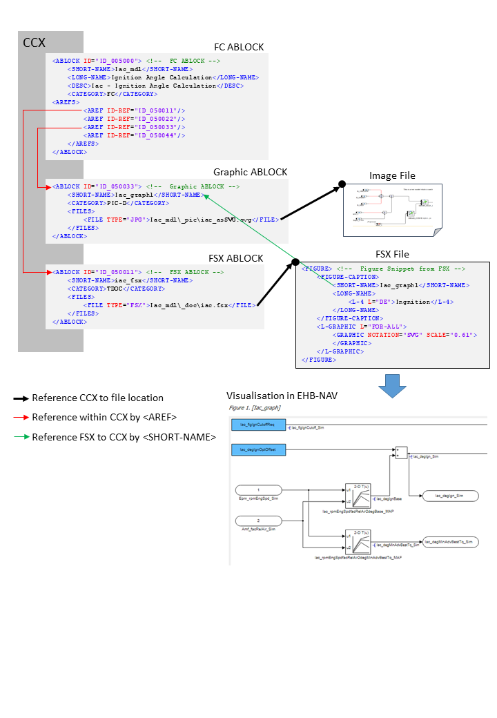
The references of the TOC ABLOCKs are visualized in EHB-NAV Document Explorer as shown in the figure below:
This will allow multiple TOCs, either with a different content or with the same content, but structured in a different way (e.g. alphabetical order and SW structure order)
TOC ABLOCK Usage
TOC ABLOCK
Referred from: Root ABLOCK
Refers to: Component ABLOCKs (BC, GC or directly to FC)
The TOC ABLOCK refer the ABLOCKs which are components (FC, BC, GC, …)
<CATEGORY>TOC
<ABLOCK ID="ID_00003">
	<SHORT-NAME>architectureView_mdl</SHORT-NAME>
	<LONG-NAME />
	<DESC>SW architecture view (Simulink models)</DESC>
	<CATEGORY>TOC</CATEGORY>
	<AREFS>
		<AREF ID-REF="ID_001000" />
		<AREF ID-REF="ID_0000301" />
		<AREF ID-REF="ID_0000302" />
		<AREF ID-REF="ID_002000" />
	</AREFS>
</ABLOCK>
A TOC block refers other structural blocks (BCs, GCs) or directly FCs.
A group of components in specific order forms the TOC. For example, the components can be grouped in alphabetical order.
A TOC ABLOCK sample with no further references to structure ABLOCKS visualized in EHB-NAV Document Explorer:
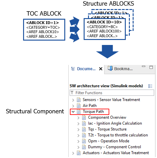
Structure ABLOCK Usage
Structure ABLOCK
Referred from: TOC ABLOCK
Refers to: another structure ABLOCK – GC ABLOCK or FC ABLOCK
The BC have references to FC’s. The category of Base Component is BC.
<CATEGORY>BC or GC
A TOC ABLOCK sample with references to structure ABLOCKS visualized in EHB-NAV Document Explorer:
<!-- TOC Structure ABLOCK -->
<ABLOCK ID="ID_0000301">
<SHORT-NAME>Air Path</SHORT-NAME>
<LONG-NAME>Air Path</LONG-NAME>
<DESC>Air Path</DESC>
<CATEGORY>GC</CATEGORY>
<AREFS>
<AREF ID-REF="ID_003000" />
<AREF ID-REF="ID_004000" />
<AREF ID-REF="ID_005000" />
<AREF ID-REF="ID_006000" />
<AREF ID-REF="ID_007000" />
<AREF ID-REF="ID_007067" />
<AREF ID-REF="ID_007077" />
</AREFS>
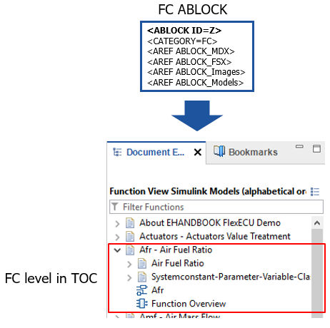
</ABLOCK>FC ABLOCK Usage
FC ABLOCK
Referred from: TOC or Component ABLOCKs – BC ABLOCK, GC ABLOCK
Refers to: leaf ABLOCK (Those ABLOCKs that refers to the actual file of information and will not refer to further ABLOCKs)
<CATEGORY>FC
<!-- FC ABLOCK -->
<ABLOCK ID="ID_005000">
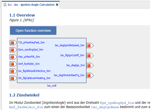
<SHORT-NAME>Iac_mdl</SHORT-NAME>
<LONG-NAME>Ignition Angle Calculation</LONG-NAME>
<DESC>Iac - Ignition Angle Calculation</DESC>
<CATEGORY>FC</CATEGORY>
<AREFS>
<AREF ID-REF="ID_050011"/>
<AREF ID-REF="ID_050022"/>
<AREF ID-REF="ID_050033"/>
<AREF ID-REF="ID_050044"/>
</AREFS>
</ABLOCK>This is the building block of CCX file, which has the references to actual files, source of information for the container. Each of the FC has <SHORT-NAME>, <LONG-NAME>, <DESC> (description) and <CATEGORY>. The category name is FC. As a TOC entry, the content of the <DESC> tag is shown in EHB-NAV later.
A FC ABLOCK sample visualized in EHB-NAV Document Explorer:
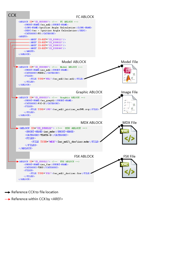
FC to Files Mapping
FC ABLOCK can refer to leaf ABLOCKs, which are defining the name and location of a file (1.-5.) or a function list for a function overview (6.):
-
MDX ABLOCK → path to MDX file
-
FSX ABLOCK → path to FSX file
-
Graphic ABLOCK → path to a graphic file
-
References to static graphics
-
References to extracted graphics from model with some information about the path and sub-model path.
-
-
Model ABLOCK (AXL/MDL,SLX/C-CODE) → path to model file
-
Other ABLOCK → path to other files for that component like XDI file, CDF,..
-
Function Overview ABLOCK → list of FC names
|
All file paths specified in <FILE> must be relative to the CCX file! |
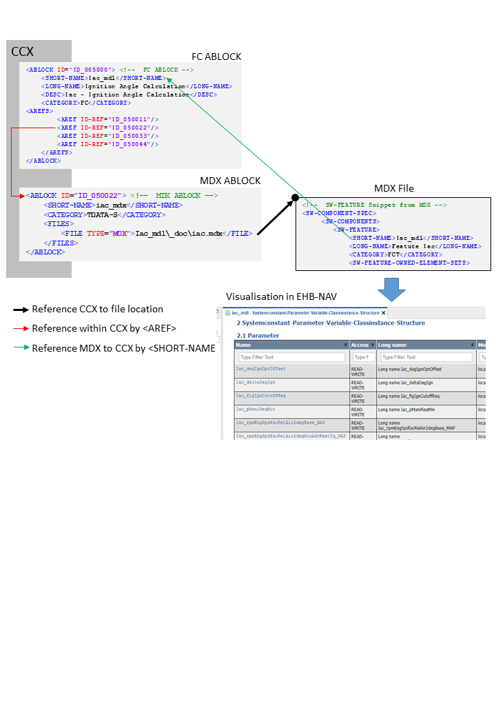
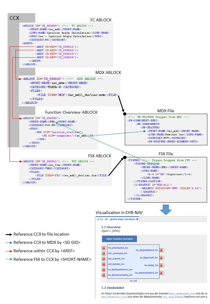
Referencing method between CCX and external files
<!-- FC ABLOCK -->
<ABLOCK ID="ID_005000">
	<SHORT-NAME>Iac_mdl</SHORT-NAME>
	<LONG-NAME>Ignition Angle Calculation</LONG-NAME>
	<DESC>Iac - Ignition Angle Calculation</DESC>
	<CATEGORY>FC</CATEGORY>
	<AREFS>
		<AREF ID-REF="ID_050011"/> (1)
		<AREF ID-REF="ID_050022"/> (2)
		<AREF ID-REF="ID_050033"/> (3)
		<AREF ID-REF="ID_050044"/> (4)
	</AREFS>
</ABLOCK>| 1 | Reference to FSX ABLOCK |
| 2 | Reference to MDX ABLOCK |
| 3 | Reference to Graphic ABLOCK |
| 4 | Reference to Model ABLOCK |
<!-- FSX ABLOCK -->
<ABLOCK ID="ID_050011">
	<SHORT-NAME>iac_fsx</SHORT-NAME>
	<CATEGORY>TDOC</CATEGORY>
	<FILES>
		<FILE TYPE="FSX">Iac_mdl\_doc\iac.fsx</FILE> (1)
	</FILES>
</ABLOCK>| 1 | Reference to FSX file |
<!-- MDX ABLOCK -->
<ABLOCK ID="ID_050022">
	<SHORT-NAME>iac_mdx</SHORT-NAME>
	<CATEGORY>TDATA-S</CATEGORY>
	<FILES>
		<FILE TYPE="MDX">Iac_mdl\_doc\iac.mdx</FILE> (1)
	</FILES>
</ABLOCK>| 1 | Reference to MDX file |
<!-- Graphic ABLOCK -->
<ABLOCK ID="ID_050033">
	<SHORT-NAME>Iac_graph1</SHORT-NAME>
	<CATEGORY>PIC-D</CATEGORY>
	<FILES>
		<FILE TYPE="JPG">Iac_mdl\_pic\iac_asSVG.svg</FILE> (1)
	</FILES>
</ABLOCK>| 1 | Reference to SVG file |
<!-- Model ABLOCK -->
<ABLOCK ID="ID_050044">
	<SHORT-NAME>iac_mdl</SHORT-NAME>
	<CATEGORY>MODEL</CATEGORY>
	<FILES>
		<FILE TYPE="MDL">Iac_mdl\Iac.mdl</FILE> (1)
	</FILES>
</ABLOCK>| 1 | Reference to Simulink model *.mdl file |
MDX ABLOCK Usage
MDX ABLOCK
Referred from: FC ABLOCK / Root ABLOCK
Refers to: none
<CATEGORY>TDATA-S or TDATA-PRO
FILE TYPE=”MDX”
<!-- MDX ABLOCK -->
<ABLOCK ID="ID_050022">
	<SHORT-NAME>iac_mdx</SHORT-NAME>
	<CATEGORY>TDATA-S</CATEGORY>
	<FILES>
		<FILE TYPE="MDX">Iac_mdl\_doc\iac.mdx</FILE>
	</FILES>
</ABLOCK>
In CCX, the FC ABLOCK is referring to its MDX file ABLOCK using AREF-ID (TDATA-S). There is also a global referring from the Root ABLOCK possible (TDATA-PRO). The relevant MDX file content is used for the model interface data and label information. To allow this, the <SHORT-NAME> of the FC ABLOCK must match to the SW-FEATURE <SHORT-NAME> in the MDX file. (Read more in chapter The MDX File Structure)
FSX ABLOCK Usage
FSX ABLOCK
Referred from: FC ABLOCK
Refers to: none
<CATEGORY>TDOC
FILE TYPE=”FSX”
<!-- FSX ABLOCK -->
<ABLOCK ID="ID_050011">
	<SHORT-NAME>iac_fsx</SHORT-NAME>
	<CATEGORY>TDOC</CATEGORY>
	<FILES>
		<FILE TYPE="FSX">Iac_mdl\_doc\iac.fsx</FILE>
	</FILES>
</ABLOCK>
In CCX, the FC ABLOCK is referring to its FSX file ABLOCK using AREF-ID. The FSX file content is then used for textual information. (Read more in chapter The FSX File Structure)
Graphic ABLOCK Usage
Graphic ABLOCK
Referred from: FC ABLOCK
Refers to: none
<CATEGORY>PIC-D
FILE TYPE=”EPS”, “PS”, “PDF”, “JPG”, “PNG”, “BMP”, “SVG”, “GIF”
<!-- Graphic ABLOCK -->
<ABLOCK ID="ID_050033">
	<SHORT-NAME>Iac.Iac_mdl</SHORT-NAME>
	<CATEGORY>PIC-D</CATEGORY>
	<SDGS>
		<SDG GID="modeldata">
			<SD GID="model">ID_050044</SD>
			<SD GID="submodel-path">Iac/Iac_mdl</SD>
		</SDG>
	</SDGS>
	<FILES>
		<FILE TYPE="JPG">Iac_mdl\_pic\iac_asSVG.svg</FILE>
	</FILES>
</ABLOCK>
The FILE TYPE has to match to the strings above. Later for further processing, the file format of the file itself is considered.
In CCX, the FC ABLOCK is referring to any graphic file ABLOCK using AREF-ID. The graphic is then embedded in the textual information. The ABLOCK may also contain the sub model path to an interactive model and a link to the model file via <SD GID=model”>ID (Read more in chapter Handling of Graphics in EHB)
|
File type PDF, PS or EPS images are processed as SVG image files. Remaining file formats are copied as is. |
Model ABLOCK Usage
Model ABLOCK
Referred from: FC ABLOCK
Refers to: none
<CATEGORY>MODEL
FILE TYPE ; (file extensions) =”AXL”; (.axl) / “SLX”; (.slx) / “MDL”; (.mdl) / “UGG”; (.ugg) / “C-CODE”; (.zip) (The zip should contain c and header files) /
”MATLAB”; (.zip)/”APP”; (.app)
<!-- Model ABLOCK -->
<ABLOCK ID="ID_050044">
	<SHORT-NAME>iac_mdl</SHORT-NAME>
	<CATEGORY>MODEL</CATEGORY>
	<FILES>
		<FILE TYPE="MDL">Iac_mdl\Iac.mdl</FILE>
	</FILES>
</ABLOCK>
In CCX, the FC ABLOCK is referring to its model file ABLOCK using AREF-ID. The model file is then converted into an interactive model. The model ABLOCK ID may also be referred from a graphic ABLOCK. (Read more in chapter Reference Model with User provided Graphic)
CDF ABLOCK Usage
CDF ABLOCK
Referred from: FC ABLOCK or Root ABLOCK +
Refers to: none
<CATEGORY>TDATA
FILE TYPE=”CDF”
<!-- CDF ABLOCK -->
<ABLOCK ID="ID_00004">
	<SHORT-NAME>globalCdfCdfx</SHORT-NAME>
	<LONG-NAME>globalCdfCdfx longname</LONG-NAME>
	<CATEGORY>TDATA</CATEGORY>
	<FILES>
		<FILE TYPE="CDF">_global\CDM.CDFX</FILE>
	</FILES>
</ABLOCK>
In CCX, the FC ABLOCK is referring to its CDF file ABLOCK using AREF-ID. There is also a global referring from the Root ABLOCK possible. The CDX file content is then used to show the values of parameters and system constants in EHB-NAV.
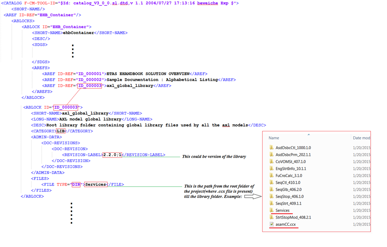
LIB ABLOCK Usage (For ASCET only)
LIB ABLOCK
Referred from: Root ABLOCK +
Refers to: none
<CATEGORY>LIB
FILE TYPE=”DIR”
<!-- LIB ABLOCK -->
<ABLOCK ID="ID_000001">
	<SHORT-NAME>Services_ID1</SHORT-NAME>
	<LONG-NAME>Global model library</LONG-NAME>
	<CATEGORY>LIB</CATEGORY>
	<FILES>
		<FILE TYPE="DIR">..\LibDir</FILE>
	</FILES>
</ABLOCK>
In CCX, the Root ABLOCK is referring to its LIB folder ABLOCK using AREF-ID. The library folder points to a root directory folder structure, which is containing global library files, used in all ASCET models. (Read more in chapter ASCET Model Reference to global Library and other Sub-Components)
Function Overview ABLOCK Usage
Function Overview ABLOCK
Referred from: FSX by FIGURE-SHORT-NAME
Refers to: FC SHORT-NAME in MDX
<CATEGORY>PIC-FO
<SDG GID=“function_overview”
<!-- Function Overview ABLOCK -->
<ABLOCK ID="EpmXfn">
	<SHORT-NAME>Epm Function Overview</SHORT-NAME>
	<CATEGORY>PIC-FO</CATEGORY>
	<SDGS>
		<SDG GID="function_overview">
			<SD GID="component">Epm</SD>
		</SDG>
	</SDGS>
</ABLOCK>
This ABLOCK defines a list of FCs by using the <SD GID=”component”>FC_Name tag. The <SHORT-NAME> of the ABLOCK should correspond to the FIGURE’s <SHORT-NAME> in FSX. In addition, the <SD GID FC_Name> should match to the corresponding SW-FEATURE <SHORT-NAME> in MDX. This will allow a function overview graphic at this FSX location in EHB-NAV. (Read more in chapter Function Overview Graphic)
ARXML ABLOCK Usage
As an alternative to MDX, EHB-CB supports AUTOSAR Classic meta-data information as input. Here function interface descriptions has to be defined in an AUTOSAR file (.arxml), which then has be referenced in the catalog file (CCX).
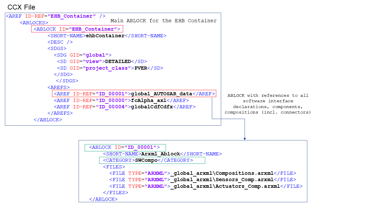
 ARXML ABLOCK
Referred from: Root ABLOCK
 Refers to: ARXML containing Software interface declaration, Components, Compositions
 <CATEGORY>SWCompo
 FILE TYPE=”ARXML”
Create an ABLOCK with category SWCompo, which references to .arxml file(s) containing function interface description. Add reference to the created ABLOCK from main ABLOCK for the EHB Container
Alternatively AUTOSAR data (in the form of ARXML)can be referenced from a component to which it belongs.
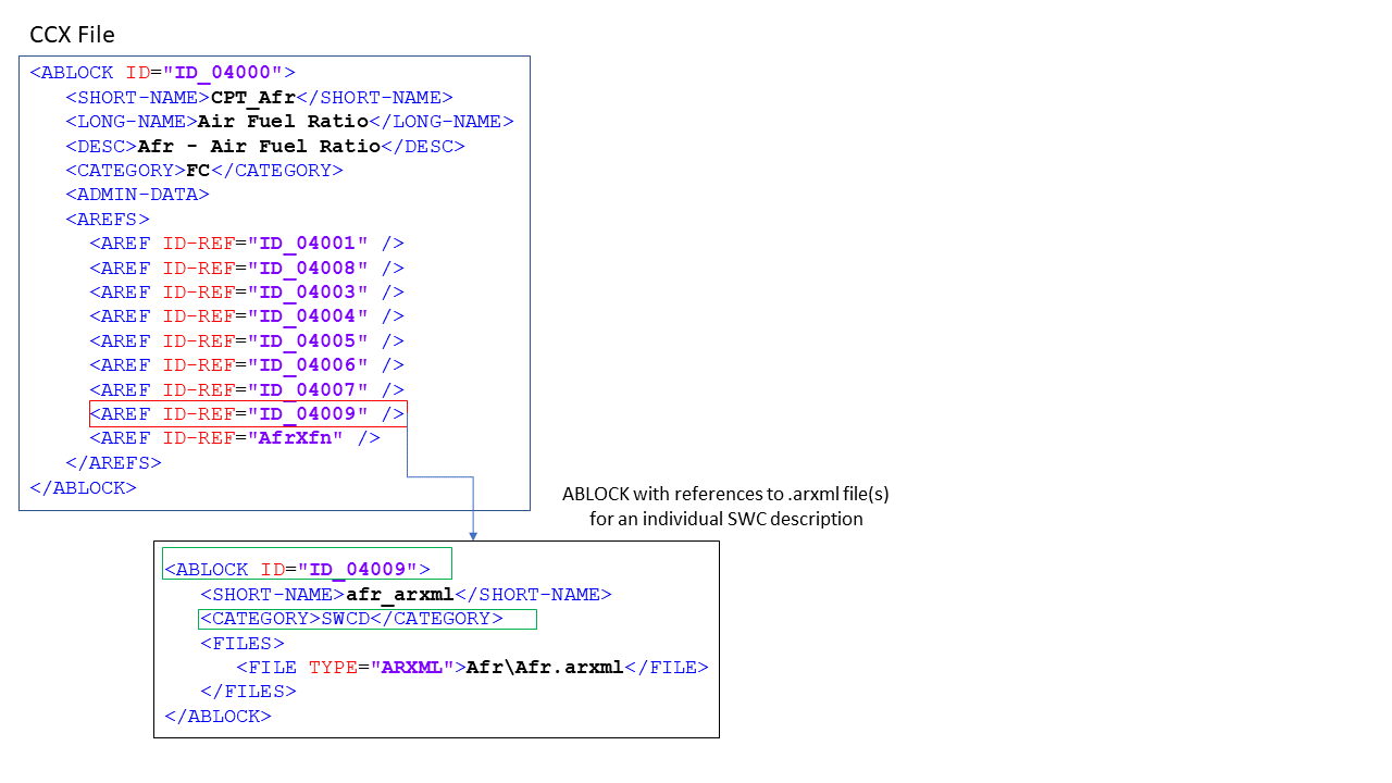
 ARXML ABLOCK
Referred from: Component ABLOCK
 Refers to: ARXML containing Software interface declaration, Components, Compositions
 <CATEGORY>SWCD
 FILE TYPE=”ARXML”
Create an ABLOCK with category SWCD, which references to .arxl file(s) containing function interface description. Add reference to the created ABLOCK from docu unit (component). Finally reference the docu unit in main ABLOCK for EHB container
<!-- MDX ABLOCK -->
<ABLOCK ID="ID_050022">
	<SHORT-NAME>iac_mdx</SHORT-NAME>
	<CATEGORY>TDATA-S</CATEGORY>
	<FILES>
		<FILE TYPE="MDX">Iac_mdl\_doc\iac.mdx</FILE>
	</FILES>
</ABLOCK>
In CCX, the FC ABLOCK is referring to its MDX file ABLOCK using AREF-ID (TDATA-S). There is also a global referring from the Root ABLOCK possible (TDATA-PRO). The relevant MDX file content is used for the model interface data and label information. To allow this, the <SHORT-NAME> of the FC ABLOCK must match to the SW-FEATURE <SHORT-NAME> in the MDX file. (Read more in chapter The MDX File Structure)
The MDX File Structure
The MDX file contains information about variables, parameters, system constants and class instances. This meta data (like imported/exported/local, compu-method, data-type, …) of labels is stored in an internal database of the EHB container.
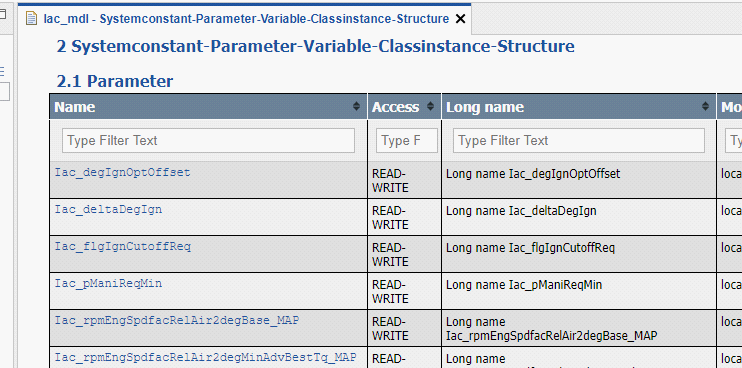
In addition, the standard chapters Systemconstant-Parameter-Variable-Classinstance-Structure for each FC are created out of this data.
|
The appearance of these standard chapters can be configured in a flexible way. For details please refer to the chapter Label table configuration in the EHB-CB User Guide. |
Furthermore, the MDX content is used for properties view, label pop-up, auto-tagging and search proposal dialog in EHB-NAV.
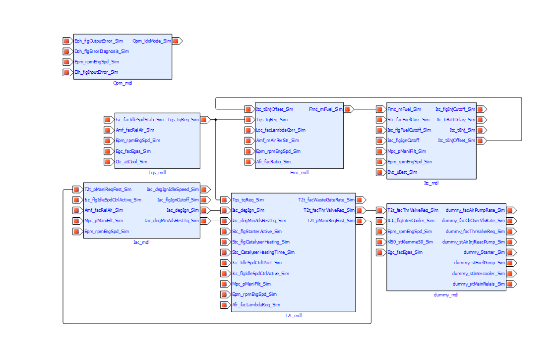
Another NAV feature supported using MDX information is the “Function Overview”. It provides mapping between the FC’s in the whole container and how all the element labels are related. This works name based.
Example in EHB-NAV:
The MDX format for EHB in detail:
All variables, parameters and system constants have to be defined in the global <SW-DATA-DICTONARY-SPEC>, their meta data will be specified in the section <SW-DATA-DEF-PROPS>.
<SW-DATA-DICTIONARY-SPEC>
	<SW-VARIABLES>
		<SW-VARIABLE>
			<SHORT-NAME>Amf_facRelAir_Sim</SHORT-NAME>
			<LONG-NAME>Long name Amf_facRelAir_Sim</LONG-NAME>
			<CATEGORY>VALUE</CATEGORY>
			<SW-DATA-DEF-PROPS>
				...
			</SW-DATA-DEF-PROPS>
		</SW-VARIABLE>
	</SW-VARIABLES>
	<SW-CALPRMS>
		<SW-CALPRM>
			<SHORT-NAME>Iac_degIgnOptOffset</SHORT-NAME>
			<LONG-NAME>Long name Iac_degIgnOptOffset</LONG-NAME>
			<CATEGORY>VALUE</CATEGORY>
			<SW-DATA-DEF-PROPS>
				...
			</SW-DATA-DEF-PROPS>
		</SW-CALPRM>
	</SW-CALPRMS>
</SW-DATA-DICTIONARY-SPEC>|
All labels defined in the dictionary have to be unique by their |
Per SW component, the labels defined in the dictionary, are then referred by their <SHORT-NAME> as local, exported or imported.
<SW-COMPONENT-SPEC>
	<SW-COMPONENTS>
		<SW-FEATURE>
			<SHORT-NAME>Iac_mdl</SHORT-NAME>
			<LONG-NAME>Feature Iac</LONG-NAME>
			<CATEGORY>FCT</CATEGORY>
			<SW-FEATURE-OWNED-ELEMENT-SETS>
				<SW-FEATURE-OWNED-ELEMENT-SET>
					<SW-FEATURE-ELEMENTS>
						...
					</SW-FEATURE-ELEMENTS>
				</SW-FEATURE-OWNED-ELEMENT-SET>
			</SW-FEATURE-OWNED-ELEMENT-SETS>
			<SW-FEATURE-INTERFACES>
				<SW-FEATURE-INTERFACE>
					<SHORT-NAME>Iac_Ex_mdl</SHORT-NAME>
					<CATEGORY>EXPORT</CATEGORY>
					<SW-INTERFACE-EXPORTS>
						<SW-INTERFACE-EXPORT>
							<SW-FEATURE-ELEMENTS>
								...
							</SW-FEATURE-ELEMENTS>
						</SW-INTERFACE-EXPORT>
					</SW-INTERFACE-EXPORTS>
				</SW-FEATURE-INTERFACE>
				<SW-FEATURE-INTERFACE>
					<SHORT-NAME>Iac_Im_mdl</SHORT-NAME>
					<CATEGORY>IMPORT</CATEGORY>
					<SW-INTERFACE-IMPORTS>
						<SW-INTERFACE-IMPORT>
							<SW-FEATURE-ELEMENTS>
								...
							</SW-FEATURE-ELEMENTS>
						</SW-INTERFACE-IMPORT>
					</SW-INTERFACE-IMPORTS>
				</SW-FEATURE-INTERFACE>
			</SW-FEATURE-INTERFACES>
		</SW-FEATURE>
		...
Structures in MDX
EHANDBOOK supports configuration of structure data types for Simulink. Structures are mapped to Simulink buses and visualized in EHB-NAV in the label popup. Structures can be defined in MDX following the MDX specification. EHANDBOOK supports the following subset of MDX:
-
STRUCTURE - SW-VARIABLE
-
STRUCTURE - SW-CALPRM
The structure name and member names must match to the Simulink bus names. Structures are defined in the global data dictionary in the same way as other variables or parameters, but in a hierarchical construct. Variable with CATEGORY “STRUCTURE” contains <SW-VARIABLES> tag under which other variables are defined. This head SW-VARIABLE becomes the ‘structure’ and the children SW-VARIABLEs become members to it.
<!-- MDX Snippet for structs -->
<SW-VARIABLE>
	<SHORT-NAME>subBus</SHORT-NAME>
	<LONG-NAME>subBus longName</LONG-NAME>
	<CATEGORY>STRUCTURE</CATEGORY>
	<SW-DATA-DEF-PROPS>
		<SW-ADDR-METHOD-REF>VAR_INIT</SW-ADDR-METHOD-REF>
		<SW-CALIBRATION-ACCESS>READ-ONLY</SW-CALIBRATION-ACCESS>
	</SW-DATA-DEF-PROPS>
	<SW-VARIABLES>
		<SW-VARIABLE>
			<SHORT-NAME>chirp</SHORT-NAME>
			<LONG-NAME>chirp Signal</LONG-NAME>
			<CATEGORY>VALUE</CATEGORY>
			<SW-DATA-DEF-PROPS>
				<SW-ADDR-METHOD-REF>VAR_INIT</SW-ADDR-METHOD-REF>
				<SW-CALIBRATION-ACCESS>READ-ONLY</SW-CALIBRATION-ACCESS>
			</SW-DATA-DEF-PROPS>
		</SW-VARIABLE>
		<SW-VARIABLE>
			<SHORT-NAME>sine</SHORT-NAME>
			<LONG-NAME>sine wave</LONG-NAME>
			<CATEGORY>VALUE</CATEGORY>
			<SW-DATA-DEF-PROPS>
				<SW-ADDR-METHOD-REF>VAR_CLEARED</SW-ADDR-METHOD-REF>
				<SW-CALIBRATION-ACCESS>READ-ONLY</SW-CALIBRATION-ACCESS>
			</SW-DATA-DEF-PROPS>
		</SW-VARIABLE>
	</SW-VARIABLES>
</SW-VARIABLE>
Naming convention and rules:
In the above example SW-VARIABLE subBus becomes the ‘structure’ and SW-VARIABLE chirp and sine become its members. Internally in EHANDBOOK we store the members along with its structure name, for example “subBus.chirp” and “subBus.sine”.
The delimiter ‘.’ dot is used for combining the structure and member names.
SW-VARIABLE structure cannot contain another SW-VARIABLE structure inside it. Nesting of structures are not allowed as per the MDX specifications (see mdx_v1.3.0.xsd).
The member names of a structure can repeat with different structures. It only needs to be unique within its structure. For example, structure1.sine and structure2.sine can exist.
The referring between the structure and the FC component works also in the same way as other variables via their <SHORT-NAME>:
<SW-COMPONENT-SPEC>
	<SW-COMPONENTS>
		<SW-FEATURE>
			<SHORT-NAME>Iac_mdl</SHORT-NAME>
			<LONG-NAME>Feature Iac</LONG-NAME>
			<CATEGORY>FCT</CATEGORY>
			<SW-FEATURE-OWNED-ELEMENT-SETS>
				<SW-FEATURE-OWNED-ELEMENT-SET>
					<SW-FEATURE-ELEMENTS>
						<SW-VARIABLE-REF>subBus</SW-VARIABLE-REF>
					</SW-FEATURE-ELEMENTS>
				</SW-FEATURE-OWNED-ELEMENT-SET>
			</SW-FEATURE-OWNED-ELEMENT-SETS>
SW-VARAIBLE of category STRUCTURE are referenced to a SW-FEATURE using the <SW-FEATURE-INTERFACES> with “IMPORT”, “EXPORT” categories or <SW-FEATURE-OWNED-ELEMENT-SETS> (=local). From the above example subBus will be treated as local for the SW-FEATURE under which it is defined.
EHANDBOOK does not derive the relation between the SW-FEATURE and the structure members. Users have to explicitly add an entry of a structure.member in the REFERENCES for establishing the import/export category. For example subBus.sine won’t appear as local in the EHANBDOOK context unless the user enters subBus.sine as a SW-VARIABLE-REF.
One MDX File per FC
In CCX, the FC ABLOCK is referring to its MDX file ABLOCK using AREF-ID. The reference from the FC ABLOCK in CCX to its related content in the MDX file is done by <SHORT-NAME>. The SW-FEATURE <SHORT-NAME> in MDX must be same as the FC <SHORT-NAME> in the CCX file.
The result in EHB-NAV is the standard chapter “Systemconstant-Parameter-Variable-Classinstance-Structure “ with the corresponding table to appear, as shown below:
Referencing method between CCX and individual MDX per FC
<!-- FC ABLOCK -->
<ABLOCK ID="ID_005000">
	<SHORT-NAME>Iac_mdl</SHORT-NAME>
	<LONG-NAME>Ignition Angle Calculation</LONG-NAME>
	<DESC>Iac - Ignition Angle Calculation</DESC>
	<CATEGORY>FC</CATEGORY>
	<AREFS>
		<AREF ID-REF="ID_050011"/>
		<AREF ID-REF="ID_050022"/> (1)
		<AREF ID-REF="ID_050033"/>
		<AREF ID-REF="ID_050044"/>
	</AREFS>
</ABLOCK>| 1 | Reference to MDX ABLOCK |
<!-- MDX ABLOCK -->
<ABLOCK ID="ID_050022">
	<SHORT-NAME>iac_mdx</SHORT-NAME>
	<CATEGORY>TDATA-S</CATEGORY>
	<FILES>
		<FILE TYPE="MDX">Iac_mdl\_doc\iac.mdx</FILE> (1)
	</FILES>
</ABLOCK>| 1 | Reference to MDX File |
<!--  SW-FEATURE Snippet from MDX -->
<SW-COMPONENT-SPEC> (1)
	<SW-COMPONENTS>
		<SW-FEATURE>
			<SHORT-NAME>Iac_mdl</SHORT-NAME> (2)
			<LONG-NAME>Feature Iac</LONG-NAME>
			<CATEGORY>FCT</CATEGORY>
			<SW-FEATURE-OWNED-ELEMENT-SETS>
...| 1 | See Visualisation in EHB-NAV |
| 2 | Short name matches with FC ABLOCK |
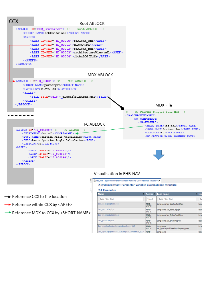
One global MDX File
Besides individual MDX files for each FC, there is also the possibility to use one common MDX file for all function components in the whole container.
This global MDX file is defined in a separate ABLOCK in CCX in the same way as for the individual ones per FC, but linked in a different way:
It has to be referenced with its ID as an additional TOC entry in the CCX in AREFS. The CATEGORY has to be TDATA-PRO, and will look as follows:
Referencing method between CCX and global MDX
<!-- Root ABLOCK -->
<ABLOCK ID="EHB_Container">
	<SHORT-NAME>ehbContainer</SHORT-NAME>
	<AREFS>
		<AREF ID-REF="ID_00000">fcAlpha_axl</AREF>
		<AREF ID-REF="ID_00001">TDATA-PRO</AREF> (1)
		<AREF ID-REF="ID_00002">fcAlpha_mdl</AREF>
		<AREF ID-REF="ID_00003">architectureView_mdl</AREF>
		<AREF ID-REF="ID_00004">globalCdfCdfx</AREF>
	</AREFS>
</ABLOCK>| 1 | Reference to MDX ABLOCK |
<!-- MDX ABLOCK -->
<ABLOCK ID="ID_00001">
	<SHORT-NAME>pavastpro</SHORT-NAME>
	<CATEGORY>TDATA-PRO</CATEGORY>
	<FILES>
		<FILE TYPE="MDX">_global\FlexEcu.xml</FILE> (1)
	</FILES>
</ABLOCK>| 1 | Reference to MDX File |
<!-- SW-FEATURE Snippet from MDX -->
<SW-COMPONENT-SPEC> (1)
	<SW-COMPONENTS>
		<SW-FEATURE>
			<SHORT-NAME>Iac_mdl</SHORT-NAME> (2)
			<LONG-NAME>Feature Iac</LONG-NAME>
			<CATEGORY>FCT</CATEGORY>
<SW-FEATURE-OWNED-ELEMENT-SETS>| 1 | See Visualisation in EHB-NAV |
| 2 | Short name matches with FC ABLOCK |
<!-- FC ABLOCK -->
<ABLOCK ID="ID_005000">
<SHORT-NAME>Iac_mdl</SHORT-NAME>
<LONG-NAME>Ignition Angle Calculation</LONG-NAME>
<DESC>Iac-Ignition Angle Calculation</DESC>
<CATEGORY>FC</CATEGORY>
<AREFS>
<AREF ID-REF="ID_050011"/>
<AREF ID-REF="ID_050033"/>
<AREF ID-REF="ID_050044"/>
</AREFS>
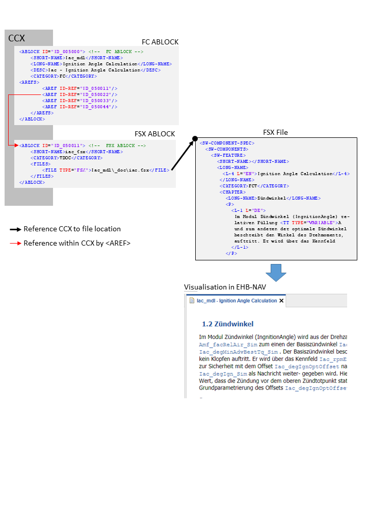
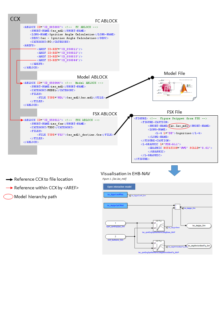
</ABLOCK>The FSX File Structure
The FSX files provides all the text content and documentation for the corresponding function component. It has also references to graphic files if any.
|
As the EHB solution is using its own numbering system, the original numbering of chapters and figure legends and other numbered references will be ignored |
In CCX, the FSX file is defined in the FSX ABLOCK, which is referred by the FC ABLOCK via AREF-ID:
Referencing method between CCX and FSX
<!--  FC ABLOCK -->
<ABLOCK ID="ID_005000">
	<SHORT-NAME>Iac_mdl</SHORT-NAME>
	<LONG-NAME>Ignition Angle Calculation</LONG-NAME>
	<DESC>Iac - Ignition Angle Calculation</DESC>
	<CATEGORY>FC</CATEGORY>
	<AREFS>
		<AREF ID-REF="ID_050011"/>
		<AREF ID-REF="ID_050022"/> (1)
		<AREF ID-REF="ID_050033"/>
		<AREF ID-REF="ID_050044"/>
	</AREFS>
</ABLOCK>| 1 | Reference to FSX ABLOCK |
<!-- FSX ABLOCK -->
<ABLOCK ID="ID_050011">
	<SHORT-NAME>iac_fsx</SHORT-NAME>
	<CATEGORY>TDOC</CATEGORY>
	<FILES>
		<FILE TYPE="FSX">Iac_mdl\_doc\iac.fsx</FILE> (1)
	</FILES>
</ABLOCK>| 1 | Reference to FSX File |
<SW-COMPONENT-SPEC> (1)
	<SW-COMPONENTS>
		<SW-FEATURE>
			<SHORT-NAME/>
			<LONG-NAME>
				<L-4 L="EN">Ignition Angle Calculation</L-4>
			</LONG-NAME>
			<CATEGORY>FCT</CATEGORY>
			<CHAPTER>
				<LONG-NAME>Zündwinkel</LONG-NAME>
				<P>
					<L-1 L="DE">
						Im Modul Zündwinkel (IngnitionAngle) re-
						lativen Füllung <TT TYPE="VARIABLE">A
						und zum anderen der optimale Zündwinkel
						beschreibt den Winkel des Drehmoments,
						auftritt. Er wird über das Kennfeld
					</L-1>
</P>| 1 | See Visualisation in EHB-NAV |
The textual content is defined below the tag <CHAPTER> in FSX.
Text Styling in FSX
EHB supports the following FSX tags:
<E/>
<BR/>
<SUP/>
<SUB/>
<XDOC/>; <XFILE/>; <XREF/>
<LIST/>; <DEF_LIST/>; <LABELED_LIST/>
<TABLE/>
<FIGURE/>
<FORMULA/>
<P/>
<DESC/>
<NOTE/>
<FT/>
<VERBATIM/>
<STATE/>
<L_1/>; <L_2/>; <L_4/>; <L_5/>; <L_10/>
<TT/>
Limitations:
-
For
<E/>the attributes TYPE=”ITALIC” / “BOLDITALIC” / “BOLD” are supported only; COLOR and FONT are currently not supported -
In general, only a subset of possible attributes and combinations for the tags above might be supported
The final styling of the text is configurable via a global CSS style sheet during Container-Build. Here also the font and color of all the texts and headers can be defined. For more details, please refer to the Container Style Guide for EHB-CB document.
Handling of Graphics in EHB
Static Graphic
Static graphics are explaining images inside the textual content, which have no links to a corresponding interactive model. To allow this, the information has to be given as follows:
In CCX:
-
The FC ABLOCK references the Graphic ABLOCK and the FSX ABLOCK via
<AREF ID-REF>tags -
The Graphic ABLOCK contains the path and name of the graphic in
<FILE>
In FSX:
-
The FIGURE’s
<SHORT-NAME>has to match with the<SHORT-NAME>of the Graphic ABLOCK in CCX
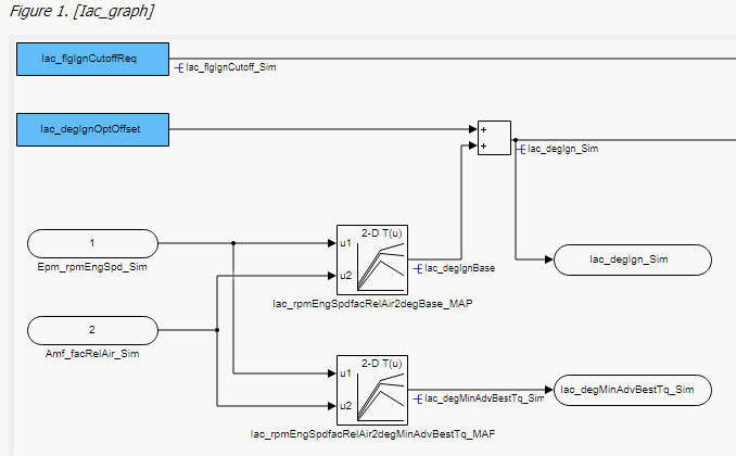
See figure below:
Reference flow diagram to show a static image
<!-- FC ABLOCK -->
<ABLOCK ID="ID_005000">
	<SHORT-NAME>Iac_mdl</SHORT-NAME>
	<LONG-NAME>Ignition Angle Calculation</LONG-NAME>
	<DESC>Iac - Ignition Angle Calculation</DESC>
	<CATEGORY>FC</CATEGORY>
	<AREFS>
		<AREF ID-REF="ID_050011"/> (1)
		<AREF ID-REF="ID_050022"/>
		<AREF ID-REF="ID_050033"/> (2)
		<AREF ID-REF="ID_050044"/>
	</AREFS>
</ABLOCK>| 1 | Reference to FSX ABLOCK |
| 2 | Reference to Graphic ABLOCK |
<!-- Graphic ABLOCK -->
<ABLOCK ID="ID_050033">
	<SHORT-NAME>Iac_graph1</SHORT-NAME>
	<CATEGORY>PIC-D</CATEGORY>
	<FILES>
		<FILE TYPE="JPG">Iac_mdl\_pic\iac_asSVG.svg</FILE> (1)
	</FILES>
</ABLOCK>| 1 | Reference to image file. |
<!-- FSX ABLOCK -->
<ABLOCK ID="ID_050011">
	<SHORT-NAME>iac_fsx</SHORT-NAME>
	<CATEGORY>TDOC</CATEGORY>
	<FILES>
		<FILE TYPE="FSX">Iac_mdl\_doc\iac.fsx</FILE> (1)
	</FILES>
</ABLOCK>| 1 | Reference to FSX File. |
<!-- Figure Snippet from FSX -->
<FIGURE> (1)
	<FIGURE-CAPTION>
		<SHORT-NAME>Iac_graph1</SHORT-NAME> (2)
		<LONG-NAME>
			<L-4 L="DE">Ingnition</L-4>
		</LONG-NAME>
	</FIGURE-CAPTION>
	<L-GRAPHIC L="FOR-ALL">
		<GRAPHIC NOTATION="SVG" SCALE="0.61">
		</GRAPHIC>
	</L-GRAPHIC>
</FIGURE>| 1 | See Visualisation in EHB-NAV |
| 2 | Short name matches with Graphic ABLOCK |
The external 3th party tool PDFFLY will be used for conversion of post script graphics (EPS, PS) to vector graphics (SVG). This tool has to be ordered separately. Raster graphics (JPEG, BMP, PNG) and vector graphics (SVG) are directly copied without the need of any 3rd party software.
ETAS recommends the usage of graphics in SVG format to allow text searching and selecting inside the graphic later on in NAV.
(Text in the SVG have to be configured within tag <TSPAN>)
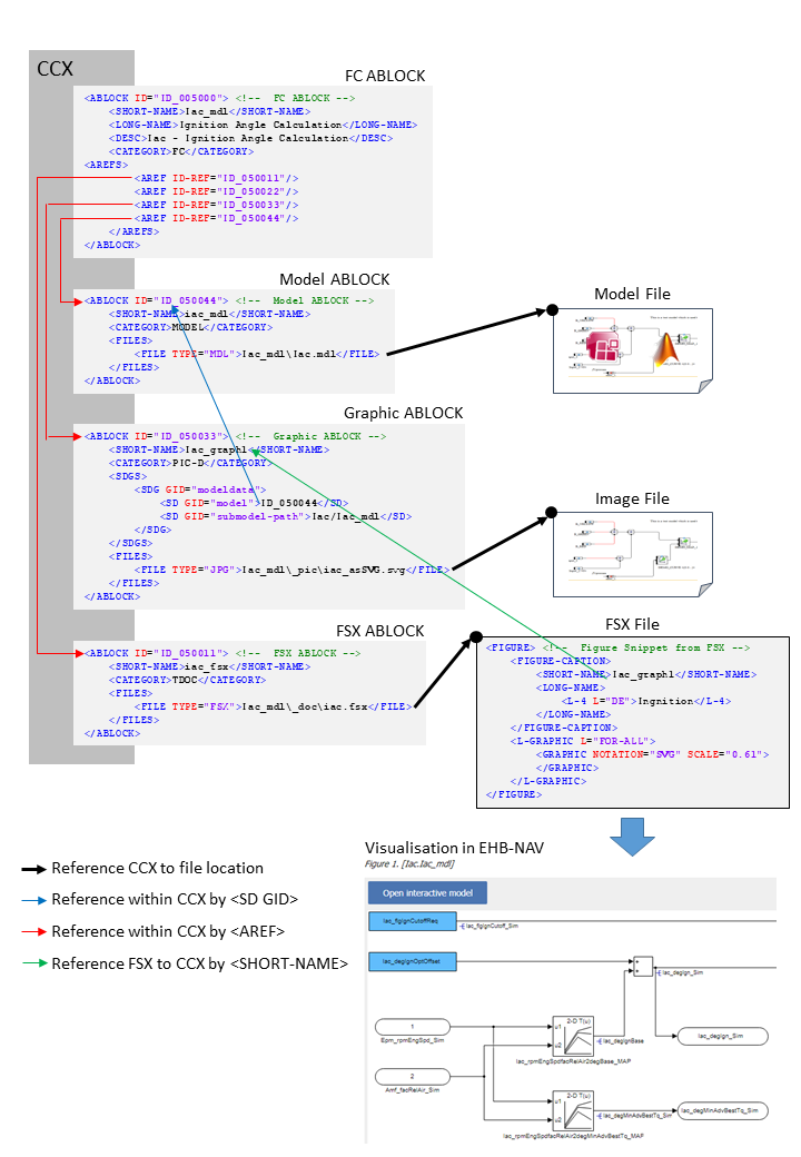
Reference Model with User provided Graphic
The graphic is extracted as a screenshot out of a specific hierarchy of a model (Simulink or ASCET) with a tool outside EHB. Therefore, a reference from the graphic to the model with some information about the path and sub-model hierarchy is required. A graphic with a model reference will appear in EHB-NAV as below:
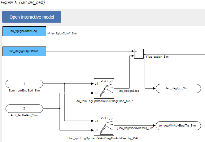
By click on “Open interactive Model”, the corresponding interactive model will be opened in EHB-NAV in exactly the same model hierarchy path.
To allow this, the information has to be given as follows:
In CCX:
-
The FC ABLOCK references the Graphic ABLOCK, the Model ABLOCK and the FSX ABLOCK via <AREF ID-REF> tags
-
The Graphic ABLOCK contains the reference ID of the Model ABLOCK in <SD GID=”model”>, the model hierarchy path in <SD GID=”submodel-path” and the path and name of the graphic in <FILE>. For model path details see chapter Model Hierarchy Path Naming Convention for Graphic Linkage.
-
The Model ABLOCK contains the directory path and file name of the model. This is an axl file having the ASCET project or an mdl/slx file for Simulink.
In FSX:
-
The FIGURE’s
<SHORT-NAME>has to match with the<SHORT-NAME>of the Graphic ABLOCK in CCX
See figure below:
Referencing flow diagram for model linkage with external graphic
<!--  FC ABLOCK -->
<ABLOCK ID="ID_005000">
	<SHORT-NAME>Iac_mdl</SHORT-NAME>
	<LONG-NAME>Ignition Angle Calculation</LONG-NAME>
	<DESC>Iac - Ignition Angle Calculation</DESC>
	<CATEGORY>FC</CATEGORY>
	<AREFS>
		<AREF ID-REF="ID_050011"/> (1)
		<AREF ID-REF="ID_050022"/>
		<AREF ID-REF="ID_050033"/> (2)
		<AREF ID-REF="ID_050044"/>
	</AREFS>
</ABLOCK>| 1 | Reference to Graphic ABLOCK. |
| 2 | Reference to FSX ABLOCK. |
<ABLOCK ID="ID_050033"> <!--  Graphic ABLOCK -->
    <SHORT-NAME>Iac_graph1</SHORT-NAME>
    <CATEGORY>PIC-D</CATEGORY>
    <FILES>
        <FILE TYPE="JPG">Iac_mdl\_pic\iac_asSVG.svg</FILE> (1)
    </FILES>
</ABLOCK>| 1 | Reference to Image File |
<ABLOCK ID="ID_050011"> <!--  FSX ABLOCK -->
    <SHORT-NAME>iac_fsx</SHORT-NAME>
    <CATEGORY>TDOC</CATEGORY>
    <FILES>
        <FILE TYPE="FSX">Iac_mdl\_doc\iac.fsx</FILE> (1)
    </FILES>
</ABLOCK>| 1 | Reference to FSX File. |
<!--  Figure Snippet from FSX -->
<FIGURE> (1)
	<FIGURE-CAPTION>
		<SHORT-NAME>Iac_graph1</SHORT-NAME>
		<LONG-NAME>
			<L-4 L="DE">Ingnition</L-4>
		</LONG-NAME>
	</FIGURE-CAPTION>
	<L-GRAPHIC L="FOR-ALL">
		<GRAPHIC NOTATION="SVG" SCALE="0.61">
		</GRAPHIC>
	</L-GRAPHIC>
</FIGURE>| 1 | See Visualisation in EHB-NAV. |
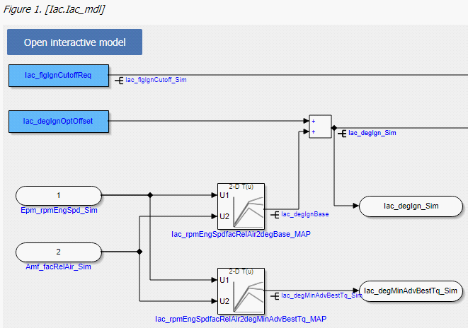
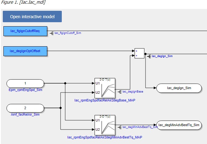
Reference Model with EHB-CB generated Graphic
Graphics appearing in the documentation, which are related to the models, can also be generated by EHB-CB during the model conversion. An auto-generated graphic will appear in EHB-NAV as below:
Advantages:
-
Exact replica of the model snap shot is generated
-
Format is SVG which allows searching and selecting of texts inside the graphic
-
No graphic screenshots from each model hierarchy have to be generated separately
-
ClickPic is supported in EHB-NAV (Navigation between images in text pane)
|
To enable this feature, the additional command line parameter -gensvg for the CB.exe has to be used. (See latest user documentation for EHB-CB) |
The linkage method between FSX and CCX is a little bit different then described before, also there some changes in the FSX:
-
In FSX, the FIGURE’s
<SHORT-NAME>for the model graphic contains the model hierarchy path directly in a mandatory format i.e. “X.Y.Z”. For details, see chapter Model Hierarchy Path Naming Convention for Graphic Linkage. -
The Graphic ABLOCK is now optional and only required if the original graphic should be used with same ASAM file set. (without -gensvg mode)
See figure below:
Referencing flow diagram for model linkage with EHB-CB generated graphic
<!--  FC ABLOCK -->
<!--  FC ABLOCK -->
<ABLOCK ID="ID_005000">
	<SHORT-NAME>Iac_mdl</SHORT-NAME>
	<LONG-NAME>Ignition Angle Calculation</LONG-NAME>
	<DESC>Iac - Ignition Angle Calculation</DESC>
	<CATEGORY>FC</CATEGORY>
	<AREFS>
		<AREF ID-REF="ID_050011"/> (1)
		<AREF ID-REF="ID_050022"/>
		<AREF ID-REF="ID_050033"/>
		<AREF ID-REF="ID_050044"/> (2)
	</AREFS>
</ABLOCK>| 1 | Reference to FSX ABLOCK |
| 2 | Reference to Model ABLOCK. |
<!-- Model ABLOCK -->
<ABLOCK ID="ID_050044">
	<SHORT-NAME>iac_mdl</SHORT-NAME>
	<CATEGORY>MODEL</CATEGORY>
	<FILES>
		<FILE TYPE="MDL">Iac_mdl\Iac.mdl</FILE> (1)
	</FILES>
</ABLOCK>| 1 | Reference to e.g. ASCET or Simulink model file. |
<!-- FSX ABLOCK -->
<ABLOCK ID="ID_050011">
	<SHORT-NAME>iac_fsx</SHORT-NAME>
	<CATEGORY>TDOC</CATEGORY>
	<FILES>
		<FILE TYPE="FSX">Iac_mdl\_doc\iac.fsx</FILE> (1)
	</FILES>
</ABLOCK>| 1 | Reference to FSX File. |
<!-- Figure Snippet from FSX -->
<FIGURE> (1)
	<FIGURE-CAPTION>
		<SHORT-NAME>Iac.Iac_mdl</SHORT-NAME>
		<LONG-NAME>
			<L-4 L="DE">Ingnition</L-4>
		</LONG-NAME>
	</FIGURE-CAPTION>
	<L-GRAPHIC L="FOR-ALL">
		<GRAPHIC NOTATION="SVG" SCALE="0.61">
		</GRAPHIC>
	</L-GRAPHIC>
</FIGURE>| 1 | See Visualisation in EHB-NAV. |
NOTICE
Incomplete, wrong or differing representation of model screenshots and interactive models from source data.
During the conversion of ASCET models, Simulink/Stateflow models or C-Code to interactive models and/or SVG graphics, the generated outputs may differ from the original model visualizations. As C-Code is written in textual form while interactive models are graphical diagrams, the semantic and interpretation can differ.
The following deviations between the model and the EHANDBOOK Container content may occur:
-
Missing or wrong graphics
-
Wrong targets on linked graphics
-
Wrong model links
-
Wrong model hierarchy links
-
-
For C-Code visualizations, different interpretations and semantics
Possible root causes of these deviations are:
-
Link specification in input text does not match to model hierachy path
-
Referenced model/source files are missing
-
Matlab connection for mask generation in Simulink was broken,
-
EHB-CB tool error due to internal error or unsupported source content
-
Technical limitations, especially for representing C-Code as graphical visualization
To identify deviations:
-
Check the entries in the log file of the generated EHANDBOOK Container for Warnings and Errors
-
Check the links between SVG graphics and interactive models in the EHANDBOOK Container
It is the responsibility of the creator of the EHANDBOOK Container to check the log files generated by EHANDBOOK Container-Build and to check the outputs for wrong model references and initiate the correction in the sources.
To ensure consistency and mitigate limitations:
-
Check the release notes and the known issues of EHANDBOOK Container-Build as well as EHANDBOOK-NAVIGATOR.
-
Compare the C-Code source code with the its graphical representation in EHANDBOOK-NAVIGATOR.
Model Hierarchy Path Naming Convention for Graphic Linkage
For a proper linkage between the image and the corresponding model hierarchy, the model hierarchy path has to be named and used in a defined way.
Using EHB-CB generated graphics:
-
The model path name must be used as FSX FIGURE’s
<SHORT-NAME>. Path delimiter is ‘.’
Using external graphics:
-
The FSX FIGURE’s
<SHORT-NAME>has to match the Graphic’s ABLOCK<SHORT-NAME>in CCX -
The Graphic’s ABLOCK must contain the model path name in <SD GID=”submodel-path”. Path delimiter is ‘/’
Naming Convention for ASCET
The model path can be derived out of the Model Explorer in EHB-NAV:
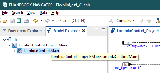
The bubble help window for the above highlighted path shows “LambdaControl_Project/Main/LambdaControl/Main”.
The first two parts _Project and Main are added by ASCET generic and could be omitted.
The remaining path is the name for the
<SD GID="submodel-path">LambdaControl/Main</SD> in the Graphic ABLOCK.
For the SHORT-NAME’s it has to be transformed to
<SHORT-NAME>LambdaControl.Main</SHORT-NAME>.
Naming Convention for Simulink
The model path can be derived directly out of the Model Explorer in EHB-NAV:
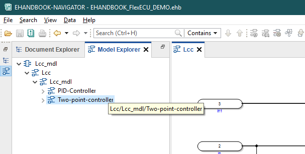
The bubble help window for the above highlighted path shows “Lcc/Lcc_mdl/Two-point-controller”.
That is the exact name for the
<SD GID="submodel-path">Lcc/Lcc_mdl/Two-point-controller</SD> in the Graphic ABLOCK.
For the SHORT-NAME’s it has to be transformed to
<SHORT-NAME>Lcc.Lcc_mdl.Two-point-controller</SHORT-NAME>.
NOTICE
Incomplete, wrong or differing representation of model screenshots and interactive models from source data.
During the conversion of ASCET models, Simulink/Stateflow models or C-Code to interactive models and/or SVG graphics, the generated outputs may differ from the original model visualizations. As C-Code is written in textual form while interactive models are graphical diagrams, the semantic and interpretation can differ.
The following deviations between the model and the EHANDBOOK Container content may occur:
-
Missing or wrong graphics
-
Wrong targets on linked graphics
-
Wrong model links
-
Wrong model hierarchy links
-
-
For C-Code visualizations, different interpretations and semantics
Possible root causes of these deviations are:
-
Link specification in input text does not match to model hierachy path
-
Referenced model/source files are missing
-
Matlab connection for mask generation in Simulink was broken,
-
EHB-CB tool error due to internal error or unsupported source content
-
Technical limitations, especially for representing C-Code as graphical visualization
To identify deviations:
-
Check the entries in the log file of the generated EHANDBOOK Container for Warnings and Errors
-
Check the links between SVG graphics and interactive models in the EHANDBOOK Container
It is the responsibility of the creator of the EHANDBOOK Container to check the log files generated by EHANDBOOK Container-Build and to check the outputs for wrong model references and initiate the correction in the sources.
To ensure consistency and mitigate limitations:
-
Check the release notes and the known issues of EHANDBOOK Container-Build as well as EHANDBOOK-NAVIGATOR.
-
Compare the C-Code source code with the its graphical representation in EHANDBOOK-NAVIGATOR.
Function Overview Graphic

It is possible to auto-generate a function overview graphic in the text pane of a FC in EHB-NAV. This overview image can be made out of one function or even out of multiple functions. Same as the interactive model screenshot also this overview graphic has a link via the “Open function overview” button to the corresponding interactive overview.
To make this possible, for every Function Overview additional entries in CCX and FSX are required.
In FSX:
-
Add a
<FIGURE>entry with unique<SHORT-NAME>at the text position, where the graphic should appear.
In CCX:
-
Add a new ABLOCK entry in the CCX file. This ABLOCK contains the details of functions chosen for the Function Overview diagram.
-
This ABLOCK must be referred by FC ABLOCK using the
<AREF-ID>tag -
The properties of the ABLOCK must be set as follows:
-
The
<SHORT-NAME>of the ABLOCK should correspond to the FIGURE’s<SHORT-NAME>in FSX -
The
<CATEGORY>must be “PIC-FO” -
The
<SDG GID>must be “function_overview” -
There must be an individual entry of SD GID=”component” for every function considered for the Function Overview diagram
-
The function names provided here should match the SW-FEATURE’s
<SHORT-NAME>of the component provided in the MDX file(s)
The [function-overview-image] below shows how this works out for one function component.
For multiple functions in the overview diagram, it works the same way. The only change is in the Function Overview ABLOCK, where now the additional functions are defined:
<ABLOCK ID="ID_012067">
	<SHORT-NAME>XFN1</SHORT-NAME>
	<CATEGORY>PIC-FO</CATEGORY>
	<SDGS>
		<SDG GID="function_overview">
			<SD GID="component">Iac_mdl</SD>
			<SD GID="component">Tqs_mdl</SD>
			<SD GID="component">T2t_mdl</SD>
		</SDG>
	</SDGS>
</ABLOCK>
In the example above, three functions Icc_mdl, Tqs_mdl and T2t_mdl are considered for the overview graphic generation.
Referencing method for single Function Overview graphic
<!-- FC ABLOCK -->
<ABLOCK ID="ID_005000">
	<SHORT-NAME>Iac_mdl</SHORT-NAME>
	<LONG-NAME>Ignition Angle Calculation</LONG-NAME>
	<DESC>Iac - Ignition Angle Calculation</DESC>
	<CATEGORY>FC</CATEGORY>
	<AREFS>
		<AREF ID-REF="ID_050011"/> (1)
		<AREF ID-REF="ID_050022"/> (2)
		<AREF ID-REF="ID_050033"/>
		<AREF ID-REF="ID_050066"/> (3)
	</AREFS>
</ABLOCK>| 1 | Reference to FSX ABLOCK. |
| 2 | Reference to MDX ABLOCK. |
| 3 | Reference to Function Overview ABLOCK. |
<!-- MDX ABLOCK -->
<ABLOCK ID="ID_050022">
	<SHORT-NAME>iac_mdx</SHORT-NAME>
	<CATEGORY>TDATA-S</CATEGORY>
	<FILES>
		<FILE TYPE="MDX">Iac_mdl\_doc\iac.mdx</FILE>  (1)
	</FILES>
</ABLOCK>| 1 | Reference to MDX File. |
<!--  SW-FEATURE Snippet from MDX -->
<SW-COMPONENT-SPEC>
	<SW-COMPONENTS>
		<SW-FEATURE>
			<SHORT-NAME>Iac_mdl</SHORT-NAME>
			<LONG-NAME>Feature Iac</LONG-NAME>
			<CATEGORY>FCT</CATEGORY>
			<SW-FEATURE-OWNED-ELEMENT-SETS>
...<ABLOCK ID="ID_050066">
<SHORT-NAME>XFN1</SHORT-NAME>
<CATEGORY>PIC-FO</CATEGORY>
<SDGS>
<SDG GID="function_overview">
<SD GID="component">Iac_mdl</SD> (1)
</SDG>
</SDGS>
</ABLOCK>| 1 | Short name matches with MDX File. |
<!-- FSX ABLOCK -->
<ABLOCK ID="ID_050011">
	<SHORT-NAME>iac_fsx</SHORT-NAME>
	<CATEGORY>TDOC</CATEGORY>
	<FILES>
		<FILE TYPE="FSX">Iac_mdl\_doc\iac.fsx</FILE> (1)
	</FILES>
</ABLOCK>| 1 | Reference to FSX File. |
<!-- Figure Snippet from FSX -->
<FIGURE> (1)
	<FIGURE-CAPTION>
		<SHORT-NAME>XFN1</SHORT-NAME> (2)
		<LONG-NAME>
			<L-4 L="DE">Ingnition</L-4>
		</LONG-NAME>
	</FIGURE-CAPTION>
	<L-GRAPHIC L="FOR-ALL">
		<GRAPHIC NOTATION="SVG" SCALE="0.61">
		</GRAPHIC>
	</L-GRAPHIC>
</FIGURE>| 1 | See Visualisation in EHB-NAV. |
| 2 | Short name matches with Function Overview ABLOCK |
NOTICE
Incomplete, wrong or differing representation of model screenshots and interactive models from source data.
During the conversion of ASCET models, Simulink/Stateflow models or C-Code to interactive models and/or SVG graphics, the generated outputs may differ from the original model visualizations. As C-Code is written in textual form while interactive models are graphical diagrams, the semantic and interpretation can differ.
The following deviations between the model and the EHANDBOOK Container content may occur:
-
Missing or wrong graphics
-
Wrong targets on linked graphics
-
Wrong model links
-
Wrong model hierarchy links
-
-
For C-Code visualizations, different interpretations and semantics
Possible root causes of these deviations are:
-
Link specification in input text does not match to model hierachy path
-
Referenced model/source files are missing
-
Matlab connection for mask generation in Simulink was broken,
-
EHB-CB tool error due to internal error or unsupported source content
-
Technical limitations, especially for representing C-Code as graphical visualization
To identify deviations:
-
Check the entries in the log file of the generated EHANDBOOK Container for Warnings and Errors
-
Check the links between SVG graphics and interactive models in the EHANDBOOK Container
It is the responsibility of the creator of the EHANDBOOK Container to check the log files generated by EHANDBOOK Container-Build and to check the outputs for wrong model references and initiate the correction in the sources.
To ensure consistency and mitigate limitations:
-
Check the release notes and the known issues of EHANDBOOK Container-Build as well as EHANDBOOK-NAVIGATOR.
-
Compare the C-Code source code with the its graphical representation in EHANDBOOK-NAVIGATOR.
ASCET Model Reference to global Library and other Sub-Components
The standard behavior is that the ASCET axl file contains the ASCET project and all needed modules and classes. An extension in the future will support also external references to sub components and global libs in other directories.
If ASCET models for any FC are referencing a global library with general classes or services, this also has to be defined in the CCX as follows:
The prerequisites for this concept are:
-
There exists exactly one main directory for the global libs (called services here) which may contain multiple subdirectories, defined in CCX as described above.
-
There is no inter FC referencing used, but a sub-class could refer to another sub-class in the same FC. So references are only possible below the main directory of the FC or in the directory (or subdirectories) of the global libs
-
There is exactly one root axl per FC, which contains the ASCET project and is referred in the CCX (name e.g. <FC_name>_p.axl)
-
File names for classes in subdirectories of the FCs could be named the same, but all names in the global lib directory and below must be unique.
Simulink Model Reference to external Library
Typically, a Simulink model is also referencing external models or libraries. EHB-CB is capable to handle this in multiple ways:
-
Reference alongside
The library or model is found if it is in the same directory level as the main model itself -
Reference by system variable
Libraries were searched in system environment variable TB_HOMEDIR, sub path \dgs_lib_mlsl and below. -
Reference defined in CCX
One search path can be defined as <SD GID> tag in the Root ABLOCK in CCX:
<ABLOCK ID="EHB_Container">
	<!-- Root ABLOCK -->
	<SHORT-NAME>ehbContainer</SHORT-NAME>
	<DESC />
	<SDGS>
		<SDG GID="global">
			<SD GID="view">Detailed</SD>
			<SD GID="project_class">PVER</SD>
			<SD GID="project_longname">ETAS FlexECU-G1 Turbo</SD>
			<SD GID="project_shortname">EHB_Demo_Container</SD>
			<SD GID="project_date">2019-07-31 10:39:00</SD>
			<SD GID="Project_variant">V7.1.1</SD>
			<SD GID="Project_revision">3</SD>
			<SD GID="info_pver">EHANDBOOK Demo</SD>
			<SD GID="doc_class">SWCALDOC</SD>
			<SD GID="language">DE</SD>
			<SD GID="hide_component">true</SD>
			<SD GID="condition">true</SD>
			<SD GID="confidential_level_2">false</SD>
			<SD GID="doctype_text">Software Documentation</SD>
			<SD GID="MATLAB_LIB_PATH">C:\source\Simulink\M160</SD>
		</SDG>
	</SDGS>
	...
There is exactly one absolute file path allowed.
-
Reference defined by parameter
A search path can be defined by the command line parameter -simlib “path”. Here even multiple paths are allowed, separated by commas -simlib “path1,path2,etc”
The order above also defines the search order for a library, but without a fallback mechanism. If a path is defined, but there is no library found, the following options will be ignored anyway. This means, only one option can be used out of number 2. – 4. from above.
For the paths defined above, also any sub path below is searched. The search path defined is valid for all models of all FCs.
There is currently no library version check implemented. The user has to provide the correct version of the libs, which fits to the models. If multiple versions of a lib are provided, CB just takes the first one found.
Links to external Resources
EHB supports URL and file links inside an FSX <CHAPTER> section.
To open an Internet page, add the following:
<P>
	<XREF>
		<LABEL-1>About ETAS EHANDBOOK</LABEL-1>
		<REFERRABLE-REF
			ID-CLASS="EXTERNAL"
			EXT-ID-CLASS="URL">https://www.etas.com/ehandbook%3c/REFERRABLE-REF%3e%3c/XREF%3e%3c/P[https://www.etas.com/ehandbook</REFERRABLE-REF>
	</XREF>
</P>
To open an external file, add the following:
<P>
	<XREF>
		<LABEL-1>Word_template</LABEL-1>
		<REFERRABLE-REF
			ID-CLASS="EXTERNAL"
			EXT-ID-CLASS="URL">file://host/path/Word_template.pdf</REFERRABLE-REF>
	</XREF>
</P>
The text inside <LABEL-1> is shown as link text in EHB-NAV. When you click on it, the “URL” will be executed with its associated Windows tool.
|
EHB only supports absolute file paths in URL. |
Attachments
|
For a general overview on attachments in EHANDBOOK, please refer to the EHANDBOOK Container-Build User Guide. |
Attachments are files associated to a documentation unit in particular a chapter in EHANDBOOK. This can be a general text chapter, a function description or a software component description.
In the ASAM-based EHB-CB approach, an <ABLOCK> with category ATTACHMENTS has to be created and linked to the documentation chapter to which the attachments shall be associated.
The 'ABLOCK' then has to list each file that represents an attachment.
<ABLOCK> (1)
    ...
    <AREFS>
        <AREF ID-REF="ID_Tqs_Attachments" /> (2)
    </AREFS>
    ...
</ABLOCK>

<ABLOCK ID="ID_Tqs_Attachments"> (3)
    <SHORT-NAME>Tqs_Attachments</SHORT-NAME>
    <CATEGORY>ATTACHMENTS</CATEGORY>
    <FILES>
        <FILE>_attachments\Tqs_Calibration_Guide.pdf</FILE> (4)
        <FILE>_attachments\Tqs_Initial_Calibration_Values.dcm</FILE> (4)
        <FILE>_attachments\Tqs_Variables_List.lab</FILE> (4)
    </FILE>
</ABLOCK>| 1 | ABLOCK of the documentation unit to which attachments shall be associated |
| 2 | Reference to the ABLOCK specifying the attachments |
| 3 | ABLOCK with category ATTACHMENTS |
| 4 | File to be attached |