Tutorial: Directory-based EHB-CB for Simulink
Introduction
Welcome to EHANDBOOK! If you don’t know about EHANDBOOK yet, check out the overview at www.etas.com/ehandbook to get a background on what EHANDBOOK is, the problems it addresses and the benefits it provides.
In this tutorial, we are going to build a small EHANDBOOK Container for a single Simulink model using the Directory-based EHANDBOOK Container-Build tool-chain.
If you are interested in ASCET models or C-Code, there are similar tutorials available as this one. Also, if you are more interested in ASAM-based XML formats for ECU software documentation, there is another EHANDBOOK Container-Build tool-chain available with a separate set of tutorials.
So let’s get started!
Installation
Prerequisites
In order to install and execute EHANDBOOK tools, you need a PC (or laptop) with Microsoft Windows 11.
You also need administrator rights to install the tools and license keys. For license keys, please contact your local ETAS sales office.
Installation of EHANDBOOK Container-Build tools
For this tutorial, we’ll use the Directory-based EHANDBOOK Container-Build tools. You can download the latest version from the ETAS Download Center.
Installation of EHANDBOOK-NAVIGATOR
To explore the generated EHB Container, you also need EHANDBOOK-NAVIGATOR installed. You can download the latest version from the ETAS Download Center.
License keys
ETAS EHANDBOOK products are protected by electonic license keys. Please ensure that you have valid license keys to operate the tools.
For trial purposes, you can obtain evaluation licenses for a limited time.
Setting up the input data
To generate EHB Containers using the Directory-based EHANDBOOK Container-Build tools, the input data such as models, interface and label descriptions as well as textual documentation must be arranged in a directory structure. The directory structure must follow a specific convention:
-
A root directory: This directory is passed to EHB-CB tool-chain as input directory
-
One or more sub-directories: Each sub-directory represents a separate function
-
Within each sub-directory, files with model data, interface and label description as well as textual description is placed
└── ECU_SW_XYZ
    ├── Function1
    │   ├── function_1_model.slx
    │   ├── interface_and_labels.xlsx
    │   └── textual_description.adoc
    .
    .
    .
    └── Function_n
        ├── function_n_model.slx
        ├── interface_and_labels.xlsx
        └── textual_description.adoc
Directory structure for the input data
Create a new directory EHB_Simulink_Example_V1 to hold the input data for the EHB Container.
Within that directory, create a sub-directory Function 1 to hold the sources of the ECU function we want to document. The sub-directory resembles a so-called documentation unit, i.e. an entity which contains all information required to document an ECU function.
Simulink model
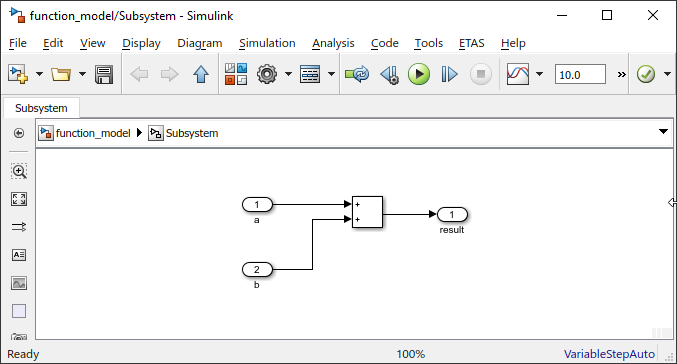
We’ll start with a small Simulink model.
You can either create your own Simulink model or download the Simulink model depicted below here.
Place the Simulink model file in the directory holding the input data the ECU function Function 1.
Your directory structure should look like this:
└── EHB_Simulink_Example_V1
    └── Function 1
       └── function_model.slx
Generating the first EHB Container
We’ll use the Directory-based EHANDBOOK Container-Build tool in GUI (Graphical User Interface) mode to generate the first EHANDBOOK Container for our example.
In the installation directory, double-click on the eHandbookCB.exe to launch the tool in GUI mode. Alternatively, invoke eHandbookCB.exe from the command line, but without any arguments.
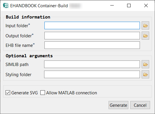
Specify the directory <path>\EHB_Simulink_Example_V1 with the input data as input directory.
Then, chose a directory where you want the generated EHB Container to be placed. A good convetion is to create a directory named outputs or EHB Containers next to the directory with the inputs.
Specify EHB_Simulink_Example_V1 as the name for the to be generated EHB Container.
Press Generate container to start the generation.
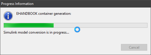
After the generation is completed, you can either open the output directory or directly open the EHB Container.
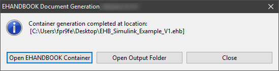
You can download the corresponding EHB Container here.
Exploring the EHB Container in EHB-NAV
Let’s open the EHB Container and inspect the example.
The EHANDBOOK Container contains exactly one ECU function - Function 1. When selecting the function in the table of contents, the chapter is empty because we have not added any textual description yet. We’ll do that later.
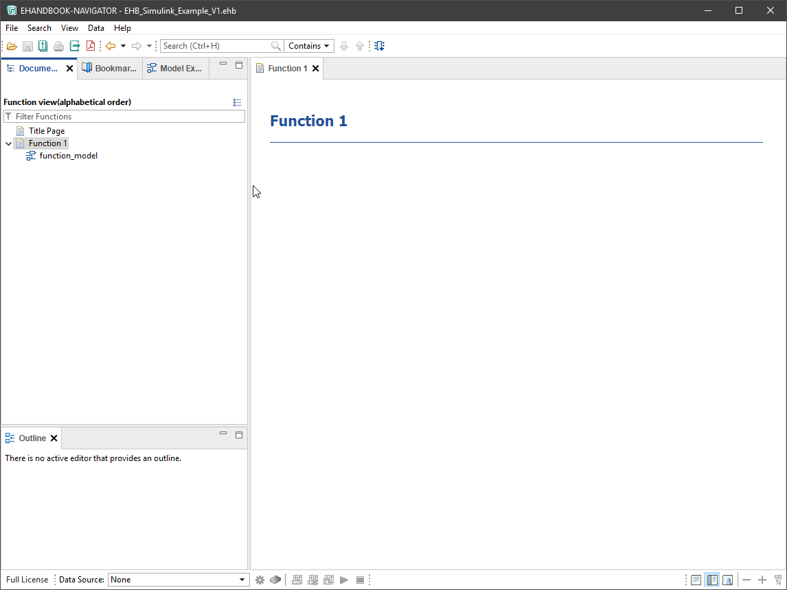
When expanding the contents of Function 1, you can see one sub-entry with a special icon:
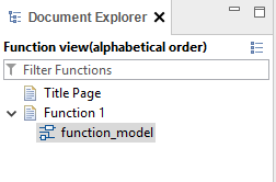
The entry links to the Simulink based interactive model.
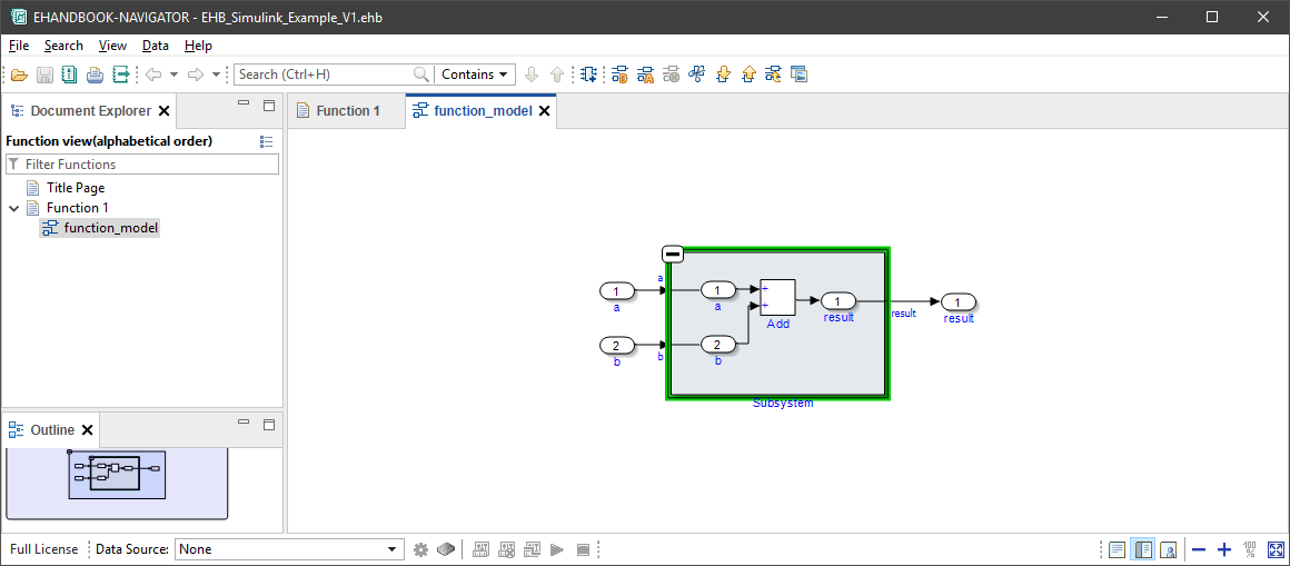
Click on the sub-entry to open the Simulink based interactive model. The model is opened in a new tab.
The Simulink-based interactive model directly resembles the original Simulink model, hence the root-level is shown.
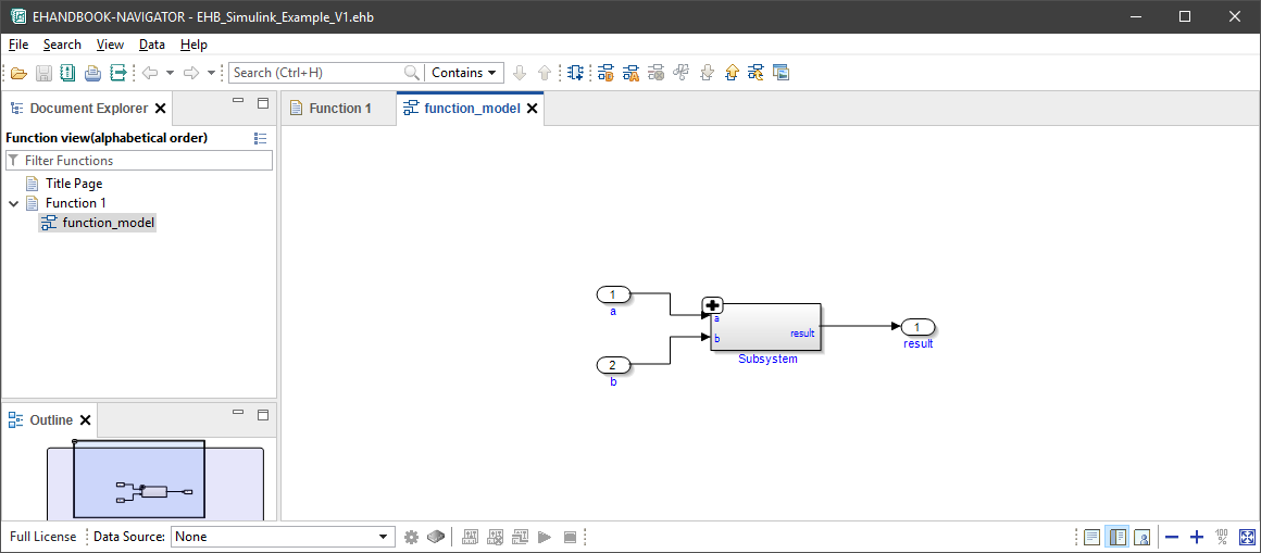
Click on the + button to expand the contents.
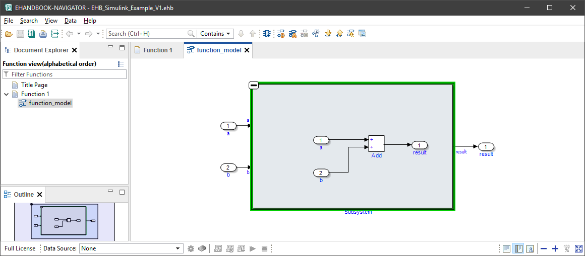
EHANDBOOK-NAVIGATOR now unfolds the contents of the subsystem and embeds them in the context. Note that there are some gaps between the input and output ports and the input and output blocks of the subsystem.
Click on the Auto-Layout button in the toolbar or select Auto Layout from the context menu.
The contents of the diagram is now layouted using an automatic layout algorithm. This also allows drawing additional connections to obtain a seamless signal flow depiction across subsystems. Also, the diagram is now more compact.
When switching to the Model Explorer, you can inspect the hierarchies of the complete ECU function as a tree view.
Summary and next steps
Our first example is already functional, but not yet complete. It lacks two more pieces of information:
-
a textual description to describe what the ECU function does
-
an interface and label specification to denote how the ECU function connects to other ECU functions
Let’s add them in the next sections.
Adding label information and interface specifciation
In our example, the function reads two variables - a and b from global memory and writes the output to a global variable result. The global variables denote the interface of the ECU function.
To document this appropriately, EHANDBOOK offers the possibility to express this information as structured tables for variables and parameters. Furthermore, a graphical visualization can be derived by means of a function overview.
Input data for label information and interface specification
To document information about the labels used by the ECU function as well as the interface specification in the EHB Container, this has to be described in the form of an Excel file which is stored in the same directory as the Simulink sources.
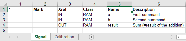
The Excel file template comes with two sheets: one for signals and one for calibrations.
Signals are global variables which can be measured with the help of measurement tools such as ETAS INCA. Signals which are read and written by an ECU function are used to exchange data with other ECU functions.
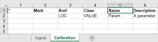
Calibrations are variables for which the values can be changed / fine-tuned with the help of calibration tools such as ETAS INCA. Calibrations can be e.g. single scalar values take the form of curves or maps which are interpreted by 1D or 2D interpolation routines.
For our example, create an Excel file with the following two sheets and store it in the directory where the Simulink file is located.
Alternatively, you can also download the filled in Excel file here.
Generating the EHANDBOOK Container
To generate the EHANDBOOK Container using the EHB-CB tool, follow the same steps as described earlier.
-
Launch the EHB-CB tool in GUI mode
-
Specify the directory with the input data as input location
-
Specify a directory as the output location
-
Start the generation
You can also download the corresponding EHB Container here.
Exploring the EHANDBOOK Container in EHB-NAV
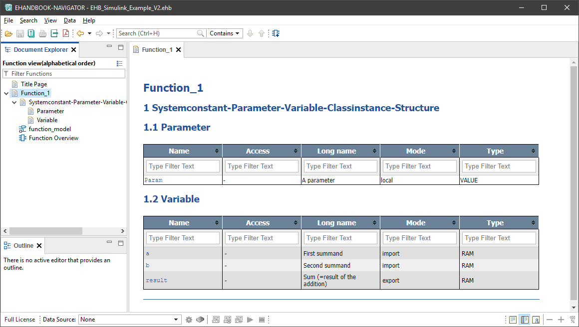
When you open the EHB Container in EHB-NAV, the first difference you will notice to the first example is that there is some textual content in the documentation for Function 1.
For signals and calibrations, EHANDBOOK Container-Build automatically generates an additional sub-section and lists the details for these labels as structured tables.
When you double-click on the entry Function Overview, a new tab is opened which shows the external interface of the ECU function as a model view.
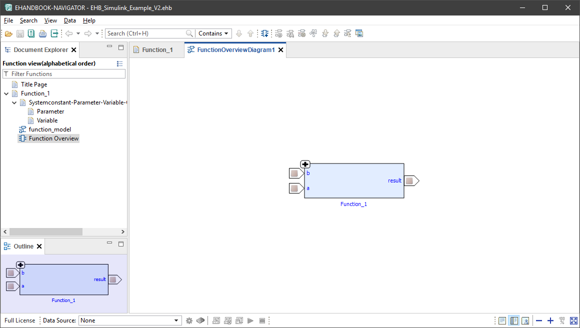
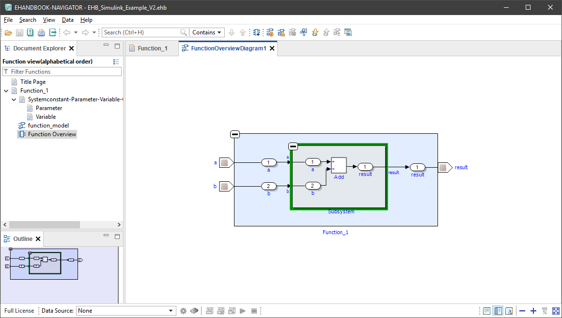
You can now start to expand the function overview block. This will expose the details of the Simulink based interactive model.
Notice that the input and output signals used by the system function_model are connected to the so-called label ports of the function overview. Through this, the ECU function can be connected to other ECU functions, establishing a seamless signal flow diagram.
Adding a textual documentation
Textual descriptions are typically used to explain the purpose of the ECU function to the reader.
Textual documentation as AsciiDoc file
To add a textual description, you have to place a document in AsciiDoc format (.adoc) in the directory of the ECU function.
You can write a new document from scratch using a text editor or IDE (e.g., Visual Studio Code) and save it as .adoc file.
EHANDBOOK supports basic features of AsciiDoc such as document structure in the form of chapters and sub-sections. You can write paragraphs, include raster images (e.g., JPEG format) and add tables.
Alternatively, you can also download an example AsciiDoc document here.
Referencing to model screenshots
In order to document ECU functions, it is often helpful to have a model screenshot followed by some textual explanation.
EHANDBOOK Container-Build can automatically generate a screenshots from Simulink based interactive models that can be embedded in the textual documentation.
To generate a screenshot, you have to create a model reference to the Simulink model and the subsystem you want to depict. This can be achieved with the EHANDBOOK model reference directive:
ehbmodelref::<simulink-model-file>/<subsystem-path>[]
For example, to obtain a model screenshot for the block diagram of the Subsystem subsystem in the Simulink model file function_model
ehbmodelref::function_model/Subsystem[]
Generating the EHANDBOOK Container
To generate the EHANDBOOK Container using the EHB-CB tool, follow the same steps as described earlier.
-
Launch the EHB-CB tool in GUI mode
-
Specify the directory with the input data as input location
-
Specify a directory as the output location
-
Start the generation
You can also download the corresponding EHB Container here.
Exploring the EHANDBOOK Container in EHB-NAV
When you open the EHB Container in EHB-NAV, the chapter now also contains a chapter Function_1 with sub-section Function Description.
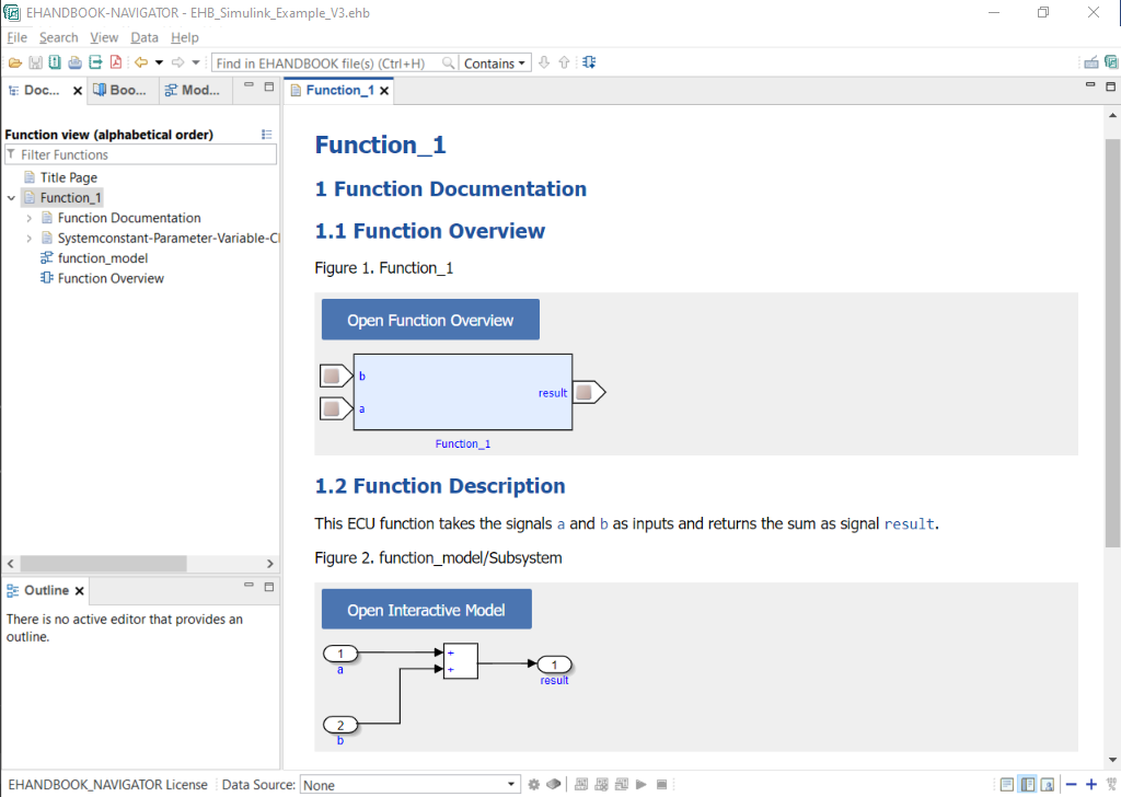
In the section Function Description, we had given a brief textual explanation of what the ECU function does. Furthermore, we had given a reference to the subsystem Subsystem. EHANDBOOK Container-Build has generated a model screenshot and integrated this a the place of the model reference.
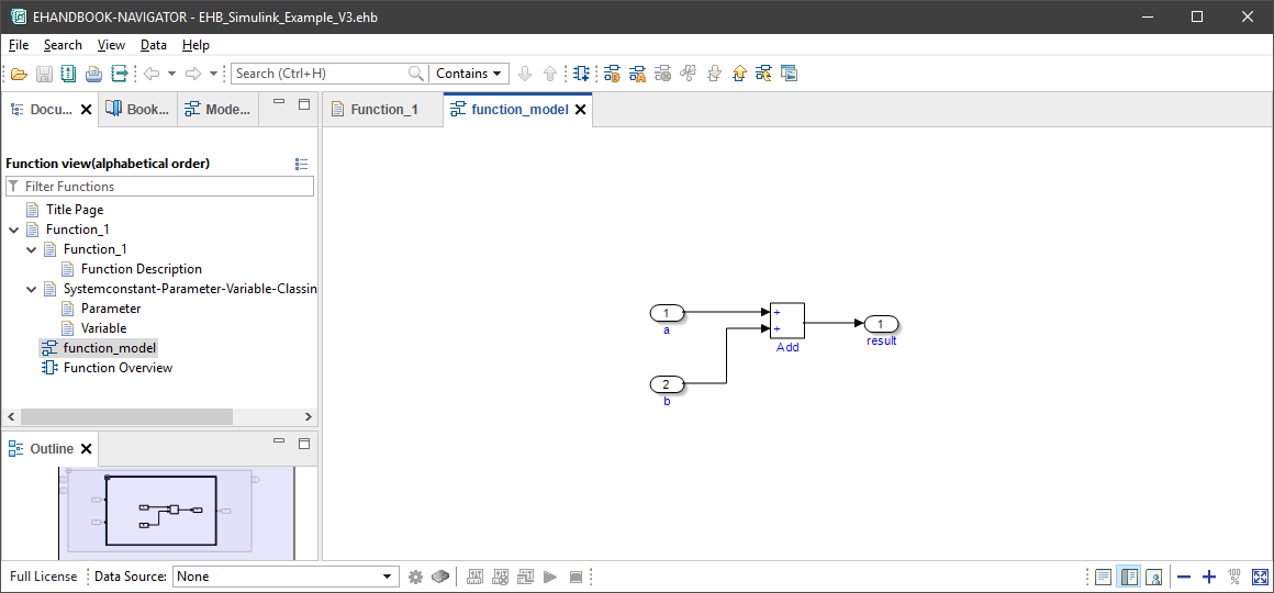
Furthermore, the model screenshot is linked to the interactive model. By clicking on the button Open interactive model, the block diagram for the subsystem is opened in a new model viewer tab where it can be further explored.
Summary
Congratulations! The example EHB Container is now complete.
The EHB Container includes a textual documentation with automatically generated model screenshot.
Furthermore, the labels of the ECU function are documented by means of structured tables. For the interface, an automatic generated function overview is available. The latter is directly linked to the interactive model which has been generated from the Simulink model.
Here are few things you can do now:
-
Create more EHB Containers with different models. You can load and combine them in EHANDBOOK-NAVIGATOR.
-
Create a single EHANDBOOK Container with multiple functions. For this, create sibling directories next to the directory for your one ECU function, add your input data and run EHB-CB.
-
Generate a PDF documentation for the contents of your EHANDBOOK Container. Check the command-line option
-pdf. -
Apply custom styling and branding to your EHANDBOOK Container.