ASAM Exchange Format: FSX and Graphics
The FSX File Structure
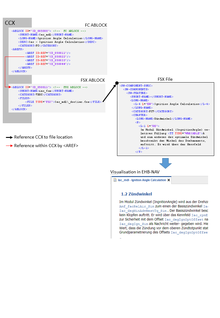
The FSX files provides all the text content and documentation for the corresponding function component. It has also references to graphic files if any.
|
As the EHB solution is using its own numbering system, the original numbering of chapters and figure legends and other numbered references will be ignored |
In CCX, the FSX file is defined in the FSX ABLOCK, which is referred by the FC ABLOCK via AREF-ID:
Referencing method between CCX and FSX
<!--  FC ABLOCK -->
<ABLOCK ID="ID_005000">
	<SHORT-NAME>Iac_mdl</SHORT-NAME>
	<LONG-NAME>Ignition Angle Calculation</LONG-NAME>
	<DESC>Iac - Ignition Angle Calculation</DESC>
	<CATEGORY>FC</CATEGORY>
	<AREFS>
		<AREF ID-REF="ID_050011"/>
		<AREF ID-REF="ID_050022"/> (1)
		<AREF ID-REF="ID_050033"/>
		<AREF ID-REF="ID_050044"/>
	</AREFS>
</ABLOCK>| 1 | Reference to FSX ABLOCK |
<!-- FSX ABLOCK -->
<ABLOCK ID="ID_050011">
	<SHORT-NAME>iac_fsx</SHORT-NAME>
	<CATEGORY>TDOC</CATEGORY>
	<FILES>
		<FILE TYPE="FSX">Iac_mdl\_doc\iac.fsx</FILE> (1)
	</FILES>
</ABLOCK>| 1 | Reference to FSX File |
<SW-COMPONENT-SPEC> (1)
	<SW-COMPONENTS>
		<SW-FEATURE>
			<SHORT-NAME/>
			<LONG-NAME>
				<L-4 L="EN">Ignition Angle Calculation</L-4>
			</LONG-NAME>
			<CATEGORY>FCT</CATEGORY>
			<CHAPTER>
				<LONG-NAME>Zündwinkel</LONG-NAME>
				<P>
					<L-1 L="DE">
						Im Modul Zündwinkel (IngnitionAngle) re-
						lativen Füllung <TT TYPE="VARIABLE">A
						und zum anderen der optimale Zündwinkel
						beschreibt den Winkel des Drehmoments,
						auftritt. Er wird über das Kennfeld
					</L-1>
</P>| 1 | See Visualisation in EHB-NAV |
The textual content is defined below the tag <CHAPTER> in FSX.
Text Styling in FSX
EHB supports the following FSX tags:
<E/>
<BR/>
<SUP/>
<SUB/>
<XDOC/>; <XFILE/>; <XREF/>
<LIST/>; <DEF_LIST/>; <LABELED_LIST/>
<TABLE/>
<FIGURE/>
<FORMULA/>
<P/>
<DESC/>
<NOTE/>
<FT/>
<VERBATIM/>
<STATE/>
<L_1/>; <L_2/>; <L_4/>; <L_5/>; <L_10/>
<TT/>
Limitations:
-
For
<E/>the attributes TYPE=”ITALIC” / “BOLDITALIC” / “BOLD” are supported only; COLOR and FONT are currently not supported -
In general, only a subset of possible attributes and combinations for the tags above might be supported
The final styling of the text is configurable via a global CSS style sheet during Container-Build. Here also the font and color of all the texts and headers can be defined. For more details, please refer to the Container Style Guide for EHB-CB document.
Handling of Graphics in EHB
Static Graphic
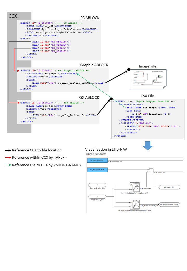
Static graphics are explaining images inside the textual content, which have no links to a corresponding interactive model. To allow this, the information has to be given as follows:
In CCX:
-
The FC ABLOCK references the Graphic ABLOCK and the FSX ABLOCK via
<AREF ID-REF>tags -
The Graphic ABLOCK contains the path and name of the graphic in
<FILE>
In FSX:
-
The FIGURE’s
<SHORT-NAME>has to match with the<SHORT-NAME>of the Graphic ABLOCK in CCX
See figure below:
Reference flow diagram to show a static image
<!-- FC ABLOCK -->
<ABLOCK ID="ID_005000">
	<SHORT-NAME>Iac_mdl</SHORT-NAME>
	<LONG-NAME>Ignition Angle Calculation</LONG-NAME>
	<DESC>Iac - Ignition Angle Calculation</DESC>
	<CATEGORY>FC</CATEGORY>
	<AREFS>
		<AREF ID-REF="ID_050011"/> (1)
		<AREF ID-REF="ID_050022"/>
		<AREF ID-REF="ID_050033"/> (2)
		<AREF ID-REF="ID_050044"/>
	</AREFS>
</ABLOCK>| 1 | Reference to FSX ABLOCK |
| 2 | Reference to Graphic ABLOCK |
<!-- Graphic ABLOCK -->
<ABLOCK ID="ID_050033">
	<SHORT-NAME>Iac_graph1</SHORT-NAME>
	<CATEGORY>PIC-D</CATEGORY>
	<FILES>
		<FILE TYPE="JPG">Iac_mdl\_pic\iac_asSVG.svg</FILE> (1)
	</FILES>
</ABLOCK>| 1 | Reference to image file. |
<!-- FSX ABLOCK -->
<ABLOCK ID="ID_050011">
	<SHORT-NAME>iac_fsx</SHORT-NAME>
	<CATEGORY>TDOC</CATEGORY>
	<FILES>
		<FILE TYPE="FSX">Iac_mdl\_doc\iac.fsx</FILE> (1)
	</FILES>
</ABLOCK>| 1 | Reference to FSX File. |
<!-- Figure Snippet from FSX -->
<FIGURE> (1)
	<FIGURE-CAPTION>
		<SHORT-NAME>Iac_graph1</SHORT-NAME> (2)
		<LONG-NAME>
			<L-4 L="DE">Ingnition</L-4>
		</LONG-NAME>
	</FIGURE-CAPTION>
	<L-GRAPHIC L="FOR-ALL">
		<GRAPHIC NOTATION="SVG" SCALE="0.61">
		</GRAPHIC>
	</L-GRAPHIC>
</FIGURE>| 1 | See Visualisation in EHB-NAV |
| 2 | Short name matches with Graphic ABLOCK |
The external 3th party tool PDFFLY will be used for conversion of post script graphics (EPS, PS) to vector graphics (SVG). This tool has to be ordered separately. Raster graphics (JPEG, BMP, PNG) and vector graphics (SVG) are directly copied without the need of any 3rd party software.
ETAS recommends the usage of graphics in SVG format to allow text searching and selecting inside the graphic later on in NAV.
(Text in the SVG have to be configured within tag <TSPAN>)
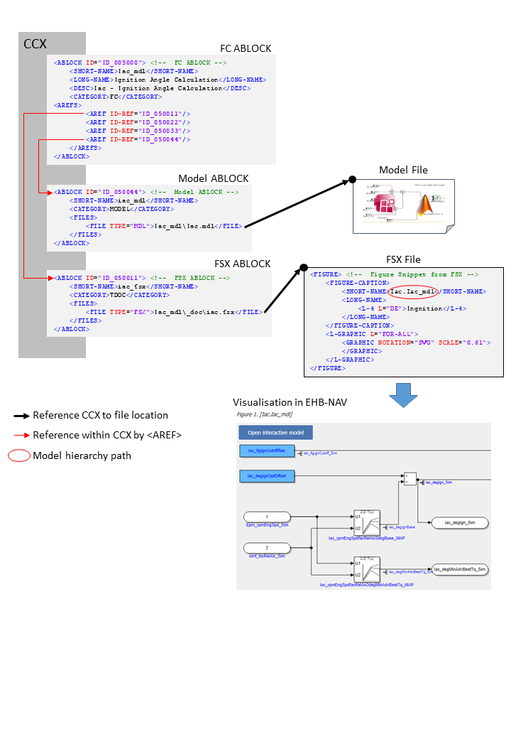
Reference Model with User provided Graphic
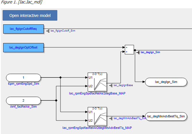
The graphic is extracted as a screenshot out of a specific hierarchy of a model (Simulink or ASCET) with a tool outside EHB. Therefore, a reference from the graphic to the model with some information about the path and sub-model hierarchy is required. A graphic with a model reference will appear in EHB-NAV as below:
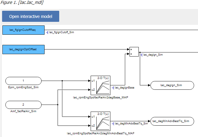
By click on “Open interactive Model”, the corresponding interactive model will be opened in EHB-NAV in exactly the same model hierarchy path.
To allow this, the information has to be given as follows:
In CCX:
-
The FC ABLOCK references the Graphic ABLOCK, the Model ABLOCK and the FSX ABLOCK via <AREF ID-REF> tags
-
The Graphic ABLOCK contains the reference ID of the Model ABLOCK in <SD GID=”model”>, the model hierarchy path in <SD GID=”submodel-path” and the path and name of the graphic in <FILE>. For model path details see chapter Model Hierarchy Path Naming Convention for Graphic Linkage.
-
The Model ABLOCK contains the directory path and file name of the model. This is an axl file having the ASCET project or an mdl/slx file for Simulink.
In FSX:
-
The FIGURE’s
<SHORT-NAME>has to match with the<SHORT-NAME>of the Graphic ABLOCK in CCX
See figure below:
Referencing flow diagram for model linkage with external graphic
<!--  FC ABLOCK -->
<ABLOCK ID="ID_005000">
	<SHORT-NAME>Iac_mdl</SHORT-NAME>
	<LONG-NAME>Ignition Angle Calculation</LONG-NAME>
	<DESC>Iac - Ignition Angle Calculation</DESC>
	<CATEGORY>FC</CATEGORY>
	<AREFS>
		<AREF ID-REF="ID_050011"/> (1)
		<AREF ID-REF="ID_050022"/>
		<AREF ID-REF="ID_050033"/> (2)
		<AREF ID-REF="ID_050044"/>
	</AREFS>
</ABLOCK>| 1 | Reference to Graphic ABLOCK. |
| 2 | Reference to FSX ABLOCK. |
<ABLOCK ID="ID_050033"> <!--  Graphic ABLOCK -->
    <SHORT-NAME>Iac_graph1</SHORT-NAME>
    <CATEGORY>PIC-D</CATEGORY>
    <FILES>
        <FILE TYPE="JPG">Iac_mdl\_pic\iac_asSVG.svg</FILE> (1)
    </FILES>
</ABLOCK>| 1 | Reference to Image File |
<ABLOCK ID="ID_050011"> <!--  FSX ABLOCK -->
    <SHORT-NAME>iac_fsx</SHORT-NAME>
    <CATEGORY>TDOC</CATEGORY>
    <FILES>
        <FILE TYPE="FSX">Iac_mdl\_doc\iac.fsx</FILE> (1)
    </FILES>
</ABLOCK>| 1 | Reference to FSX File. |
<!--  Figure Snippet from FSX -->
<FIGURE> (1)
	<FIGURE-CAPTION>
		<SHORT-NAME>Iac_graph1</SHORT-NAME>
		<LONG-NAME>
			<L-4 L="DE">Ingnition</L-4>
		</LONG-NAME>
	</FIGURE-CAPTION>
	<L-GRAPHIC L="FOR-ALL">
		<GRAPHIC NOTATION="SVG" SCALE="0.61">
		</GRAPHIC>
	</L-GRAPHIC>
</FIGURE>| 1 | See Visualisation in EHB-NAV. |
Reference Model with EHB-CB generated Graphic
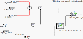
Graphics appearing in the documentation, which are related to the models, can also be generated by EHB-CB during the model conversion. An auto-generated graphic will appear in EHB-NAV as below:
Advantages:
-
Exact replica of the model snap shot is generated
-
Format is SVG which allows searching and selecting of texts inside the graphic
-
No graphic screenshots from each model hierarchy have to be generated separately
-
ClickPic is supported in EHB-NAV (Navigation between images in text pane)
|
To enable this feature, the additional command line parameter -gensvg for the CB.exe has to be used. (See latest user documentation for EHB-CB) |
The linkage method between FSX and CCX is a little bit different then described before, also there some changes in the FSX:
-
In FSX, the FIGURE’s
<SHORT-NAME>for the model graphic contains the model hierarchy path directly in a mandatory format i.e. “X.Y.Z”. For details, see chapter Model Hierarchy Path Naming Convention for Graphic Linkage. -
The Graphic ABLOCK is now optional and only required if the original graphic should be used with same ASAM file set. (without -gensvg mode)
See figure below:
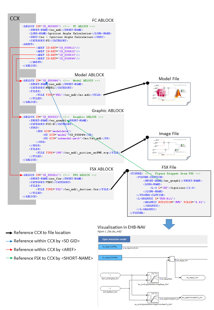
Referencing flow diagram for model linkage with EHB-CB generated graphic
<!--  FC ABLOCK -->
<!--  FC ABLOCK -->
<ABLOCK ID="ID_005000">
	<SHORT-NAME>Iac_mdl</SHORT-NAME>
	<LONG-NAME>Ignition Angle Calculation</LONG-NAME>
	<DESC>Iac - Ignition Angle Calculation</DESC>
	<CATEGORY>FC</CATEGORY>
	<AREFS>
		<AREF ID-REF="ID_050011"/> (1)
		<AREF ID-REF="ID_050022"/>
		<AREF ID-REF="ID_050033"/>
		<AREF ID-REF="ID_050044"/> (2)
	</AREFS>
</ABLOCK>| 1 | Reference to FSX ABLOCK |
| 2 | Reference to Model ABLOCK. |
<!-- Model ABLOCK -->
<ABLOCK ID="ID_050044">
	<SHORT-NAME>iac_mdl</SHORT-NAME>
	<CATEGORY>MODEL</CATEGORY>
	<FILES>
		<FILE TYPE="MDL">Iac_mdl\Iac.mdl</FILE> (1)
	</FILES>
</ABLOCK>| 1 | Reference to e.g. ASCET or Simulink model file. |
<!-- FSX ABLOCK -->
<ABLOCK ID="ID_050011">
	<SHORT-NAME>iac_fsx</SHORT-NAME>
	<CATEGORY>TDOC</CATEGORY>
	<FILES>
		<FILE TYPE="FSX">Iac_mdl\_doc\iac.fsx</FILE> (1)
	</FILES>
</ABLOCK>| 1 | Reference to FSX File. |
<!-- Figure Snippet from FSX -->
<FIGURE> (1)
	<FIGURE-CAPTION>
		<SHORT-NAME>Iac.Iac_mdl</SHORT-NAME>
		<LONG-NAME>
			<L-4 L="DE">Ingnition</L-4>
		</LONG-NAME>
	</FIGURE-CAPTION>
	<L-GRAPHIC L="FOR-ALL">
		<GRAPHIC NOTATION="SVG" SCALE="0.61">
		</GRAPHIC>
	</L-GRAPHIC>
</FIGURE>| 1 | See Visualisation in EHB-NAV. |
NOTICE
Incomplete, wrong or differing representation of model screenshots and interactive models from source data.
During the conversion of ASCET models, Simulink/Stateflow models or C-Code to interactive models and/or SVG graphics, the generated outputs may differ from the original model visualizations. As C-Code is written in textual form while interactive models are graphical diagrams, the semantic and interpretation can differ.
The following deviations between the model and the EHANDBOOK Container content may occur:
-
Missing or wrong graphics
-
Wrong targets on linked graphics
-
Wrong model links
-
Wrong model hierarchy links
-
-
For C-Code visualizations, different interpretations and semantics
Possible root causes of these deviations are:
-
Link specification in input text does not match to model hierachy path
-
Referenced model/source files are missing
-
Matlab connection for mask generation in Simulink was broken,
-
EHB-CB tool error due to internal error or unsupported source content
-
Technical limitations, especially for representing C-Code as graphical visualization
To identify deviations:
-
Check the entries in the log file of the generated EHANDBOOK Container for Warnings and Errors
-
Check the links between SVG graphics and interactive models in the EHANDBOOK Container
It is the responsibility of the creator of the EHANDBOOK Container to check the log files generated by EHANDBOOK Container-Build and to check the outputs for wrong model references and initiate the correction in the sources.
To ensure consistency and mitigate limitations:
-
Check the release notes and the known issues of EHANDBOOK Container-Build as well as EHANDBOOK-NAVIGATOR.
-
Compare the C-Code source code with the its graphical representation in EHANDBOOK-NAVIGATOR.
Model Hierarchy Path Naming Convention for Graphic Linkage
For a proper linkage between the image and the corresponding model hierarchy, the model hierarchy path has to be named and used in a defined way.
Using EHB-CB generated graphics:
-
The model path name must be used as FSX FIGURE’s
<SHORT-NAME>. Path delimiter is ‘.’
Using external graphics:
-
The FSX FIGURE’s
<SHORT-NAME>has to match the Graphic’s ABLOCK<SHORT-NAME>in CCX -
The Graphic’s ABLOCK must contain the model path name in <SD GID=”submodel-path”. Path delimiter is ‘/’
Naming Convention for ASCET
The model path can be derived out of the Model Explorer in EHB-NAV:
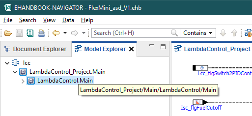
The bubble help window for the above highlighted path shows “LambdaControl_Project/Main/LambdaControl/Main”.
The first two parts _Project and Main are added by ASCET generic and could be omitted.
The remaining path is the name for the
<SD GID="submodel-path">LambdaControl/Main</SD> in the Graphic ABLOCK.
For the SHORT-NAME’s it has to be transformed to
<SHORT-NAME>LambdaControl.Main</SHORT-NAME>.
Naming Convention for Simulink
The model path can be derived directly out of the Model Explorer in EHB-NAV:
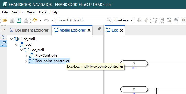
The bubble help window for the above highlighted path shows “Lcc/Lcc_mdl/Two-point-controller”.
That is the exact name for the
<SD GID="submodel-path">Lcc/Lcc_mdl/Two-point-controller</SD> in the Graphic ABLOCK.
For the SHORT-NAME’s it has to be transformed to
<SHORT-NAME>Lcc.Lcc_mdl.Two-point-controller</SHORT-NAME>.
NOTICE
Incomplete, wrong or differing representation of model screenshots and interactive models from source data.
During the conversion of ASCET models, Simulink/Stateflow models or C-Code to interactive models and/or SVG graphics, the generated outputs may differ from the original model visualizations. As C-Code is written in textual form while interactive models are graphical diagrams, the semantic and interpretation can differ.
The following deviations between the model and the EHANDBOOK Container content may occur:
-
Missing or wrong graphics
-
Wrong targets on linked graphics
-
Wrong model links
-
Wrong model hierarchy links
-
-
For C-Code visualizations, different interpretations and semantics
Possible root causes of these deviations are:
-
Link specification in input text does not match to model hierachy path
-
Referenced model/source files are missing
-
Matlab connection for mask generation in Simulink was broken,
-
EHB-CB tool error due to internal error or unsupported source content
-
Technical limitations, especially for representing C-Code as graphical visualization
To identify deviations:
-
Check the entries in the log file of the generated EHANDBOOK Container for Warnings and Errors
-
Check the links between SVG graphics and interactive models in the EHANDBOOK Container
It is the responsibility of the creator of the EHANDBOOK Container to check the log files generated by EHANDBOOK Container-Build and to check the outputs for wrong model references and initiate the correction in the sources.
To ensure consistency and mitigate limitations:
-
Check the release notes and the known issues of EHANDBOOK Container-Build as well as EHANDBOOK-NAVIGATOR.
-
Compare the C-Code source code with the its graphical representation in EHANDBOOK-NAVIGATOR.
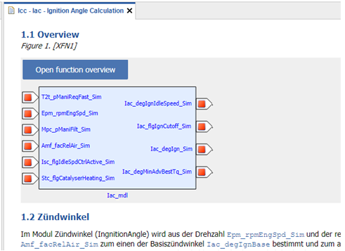
Function Overview Graphic

It is possible to auto-generate a function overview graphic in the text pane of a FC in EHB-NAV. This overview image can be made out of one function or even out of multiple functions. Same as the interactive model screenshot also this overview graphic has a link via the “Open function overview” button to the corresponding interactive overview.
To make this possible, for every Function Overview additional entries in CCX and FSX are required.
In FSX:
-
Add a
<FIGURE>entry with unique<SHORT-NAME>at the text position, where the graphic should appear.
In CCX:
-
Add a new ABLOCK entry in the CCX file. This ABLOCK contains the details of functions chosen for the Function Overview diagram.
-
This ABLOCK must be referred by FC ABLOCK using the
<AREF-ID>tag -
The properties of the ABLOCK must be set as follows:
-
The
<SHORT-NAME>of the ABLOCK should correspond to the FIGURE’s<SHORT-NAME>in FSX -
The
<CATEGORY>must be “PIC-FO” -
The
<SDG GID>must be “function_overview” -
There must be an individual entry of SD GID=”component” for every function considered for the Function Overview diagram
-
The function names provided here should match the SW-FEATURE’s
<SHORT-NAME>of the component provided in the MDX file(s)
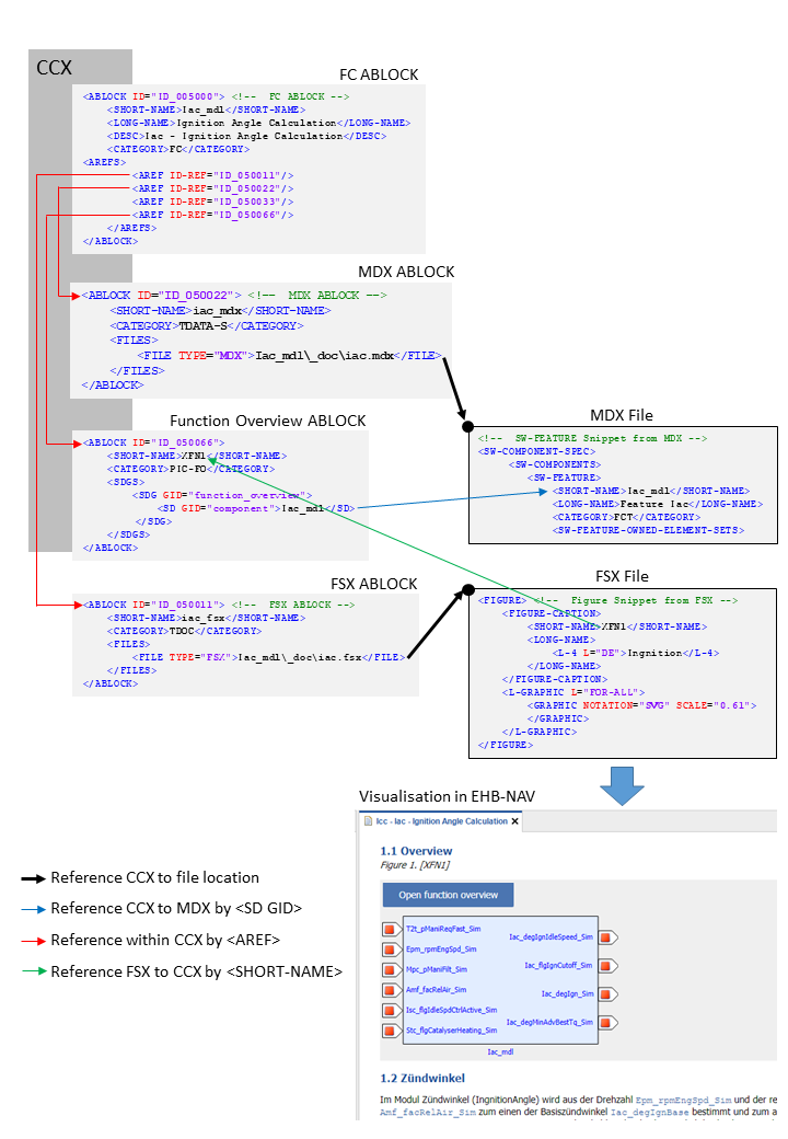
The [function-overview-image] below shows how this works out for one function component.
For multiple functions in the overview diagram, it works the same way. The only change is in the Function Overview ABLOCK, where now the additional functions are defined:
<ABLOCK ID="ID_012067">
	<SHORT-NAME>XFN1</SHORT-NAME>
	<CATEGORY>PIC-FO</CATEGORY>
	<SDGS>
		<SDG GID="function_overview">
			<SD GID="component">Iac_mdl</SD>
			<SD GID="component">Tqs_mdl</SD>
			<SD GID="component">T2t_mdl</SD>
		</SDG>
	</SDGS>
</ABLOCK>
In the example above, three functions Icc_mdl, Tqs_mdl and T2t_mdl are considered for the overview graphic generation.
Referencing method for single Function Overview graphic
<!-- FC ABLOCK -->
<ABLOCK ID="ID_005000">
	<SHORT-NAME>Iac_mdl</SHORT-NAME>
	<LONG-NAME>Ignition Angle Calculation</LONG-NAME>
	<DESC>Iac - Ignition Angle Calculation</DESC>
	<CATEGORY>FC</CATEGORY>
	<AREFS>
		<AREF ID-REF="ID_050011"/> (1)
		<AREF ID-REF="ID_050022"/> (2)
		<AREF ID-REF="ID_050033"/>
		<AREF ID-REF="ID_050066"/> (3)
	</AREFS>
</ABLOCK>| 1 | Reference to FSX ABLOCK. |
| 2 | Reference to MDX ABLOCK. |
| 3 | Reference to Function Overview ABLOCK. |
<!-- MDX ABLOCK -->
<ABLOCK ID="ID_050022">
	<SHORT-NAME>iac_mdx</SHORT-NAME>
	<CATEGORY>TDATA-S</CATEGORY>
	<FILES>
		<FILE TYPE="MDX">Iac_mdl\_doc\iac.mdx</FILE>  (1)
	</FILES>
</ABLOCK>| 1 | Reference to MDX File. |
<!--  SW-FEATURE Snippet from MDX -->
<SW-COMPONENT-SPEC>
	<SW-COMPONENTS>
		<SW-FEATURE>
			<SHORT-NAME>Iac_mdl</SHORT-NAME>
			<LONG-NAME>Feature Iac</LONG-NAME>
			<CATEGORY>FCT</CATEGORY>
			<SW-FEATURE-OWNED-ELEMENT-SETS>
...<ABLOCK ID="ID_050066">
<SHORT-NAME>XFN1</SHORT-NAME>
<CATEGORY>PIC-FO</CATEGORY>
<SDGS>
<SDG GID="function_overview">
<SD GID="component">Iac_mdl</SD> (1)
</SDG>
</SDGS>
</ABLOCK>| 1 | Short name matches with MDX File. |
<!-- FSX ABLOCK -->
<ABLOCK ID="ID_050011">
	<SHORT-NAME>iac_fsx</SHORT-NAME>
	<CATEGORY>TDOC</CATEGORY>
	<FILES>
		<FILE TYPE="FSX">Iac_mdl\_doc\iac.fsx</FILE> (1)
	</FILES>
</ABLOCK>| 1 | Reference to FSX File. |
<!-- Figure Snippet from FSX -->
<FIGURE> (1)
	<FIGURE-CAPTION>
		<SHORT-NAME>XFN1</SHORT-NAME> (2)
		<LONG-NAME>
			<L-4 L="DE">Ingnition</L-4>
		</LONG-NAME>
	</FIGURE-CAPTION>
	<L-GRAPHIC L="FOR-ALL">
		<GRAPHIC NOTATION="SVG" SCALE="0.61">
		</GRAPHIC>
	</L-GRAPHIC>
</FIGURE>| 1 | See Visualisation in EHB-NAV. |
| 2 | Short name matches with Function Overview ABLOCK |
NOTICE
Incomplete, wrong or differing representation of model screenshots and interactive models from source data.
During the conversion of ASCET models, Simulink/Stateflow models or C-Code to interactive models and/or SVG graphics, the generated outputs may differ from the original model visualizations. As C-Code is written in textual form while interactive models are graphical diagrams, the semantic and interpretation can differ.
The following deviations between the model and the EHANDBOOK Container content may occur:
-
Missing or wrong graphics
-
Wrong targets on linked graphics
-
Wrong model links
-
Wrong model hierarchy links
-
-
For C-Code visualizations, different interpretations and semantics
Possible root causes of these deviations are:
-
Link specification in input text does not match to model hierachy path
-
Referenced model/source files are missing
-
Matlab connection for mask generation in Simulink was broken,
-
EHB-CB tool error due to internal error or unsupported source content
-
Technical limitations, especially for representing C-Code as graphical visualization
To identify deviations:
-
Check the entries in the log file of the generated EHANDBOOK Container for Warnings and Errors
-
Check the links between SVG graphics and interactive models in the EHANDBOOK Container
It is the responsibility of the creator of the EHANDBOOK Container to check the log files generated by EHANDBOOK Container-Build and to check the outputs for wrong model references and initiate the correction in the sources.
To ensure consistency and mitigate limitations:
-
Check the release notes and the known issues of EHANDBOOK Container-Build as well as EHANDBOOK-NAVIGATOR.
-
Compare the C-Code source code with the its graphical representation in EHANDBOOK-NAVIGATOR.