Tutorial: Directory-based EHB-CB for Simulink
Introduction
In this tutorial, you will learn how to build a small EHANDBOOK Container for a single ECU function using Simulink and the Directory-based EHANDBOOK Container-Build tool chain.
So let’s get started!
| If you are new to Simulink, see Introduction to Simulink before starting this tutorial. |
Set Up the Input Data
To generate an EHANDBOOK Container using the Directory-based EHANDBOOK Container-Build tool chain, organize the input data in the following directory structure:
-
A root directory that is passed to the EHANDBOOK Container-Build tool chain as the input directory.
-
One or more sub-directories, where each sub-directory represents a separate ECU function.
-
Each sub-directory contains the Simulink model, interface and label descriptions, and textual documentation for that ECU function.
└── ECU_SW_XYZ
    ├── Function1
    │   ├── function_1_model.slx
    │   ├── interface_and_labels.xlsx
    │   └── textual_description.adoc
    .
    .
    .
    └── Function_n
        ├── function_n_model.slx
        ├── interface_and_labels.xlsx
        └── textual_description.adoc
Create the Input Directory Structure
Create a new directory EHB_Simulink_Example_V1 to hold the input data for the EHANDBOOK Container.
Within this directory, create a sub-directory Function 1 to hold the source files for the ECU function to be documented.
The sub-directory represents a documentation unit, which contains all the information required to document an ECU function.
Simulink Model
Start with a small Simulink model.
You can either create your own Simulink model or download the example model here.
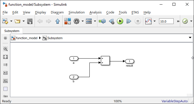
Place the Simulink model file in the Function 1 directory.
Your directory structure should look like this:
└── EHB_Simulink_Example_V1
    └── Function 1
       └── function_model.slx
Adding Label Information and Interface Specification
In this example, the function reads the global variables a and b and writes the output to the global variable result. These global variables define the interface of the ECU function.
EHANDBOOK uses structured tables to document signals and calibrations. It can also generate a Function Overview from this information.
Prepare the Excel File
To document the signals and interface information, create an Excel file and store it in the same directory as the Simulink model.
The Excel template contains two sheets:
-
Signals – Used to describe the signals that are read or written by the ECU function.
-
Calibrations – Used to describe the calibration parameters of the ECU function.
For this example, create an Excel file with the following two sheets and save it in the Function 1 directory.
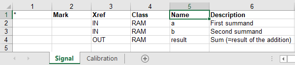
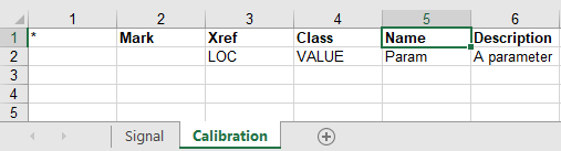
Alternatively, you can download the completed Excel file here.
Adding Textual Documentation
Textual documentation is used to explain the purpose and functionality of the ECU function.
Textual Documentation as an AsciiDoc File
To add textual documentation, create an AsciiDoc (.adoc) file and place it in the directory of the ECU function.
You can create the file by:
-
Writing a new document using a text editor or an IDE (for example, Visual Studio Code).
-
Saving the document with the
.adocextension.
EHANDBOOK supports basic AsciiDoc features, including:
-
Headings and sections
-
Paragraphs
-
Images
-
Tables
Alternatively, you can download an example AsciiDoc document.
Referencing Model Screenshots
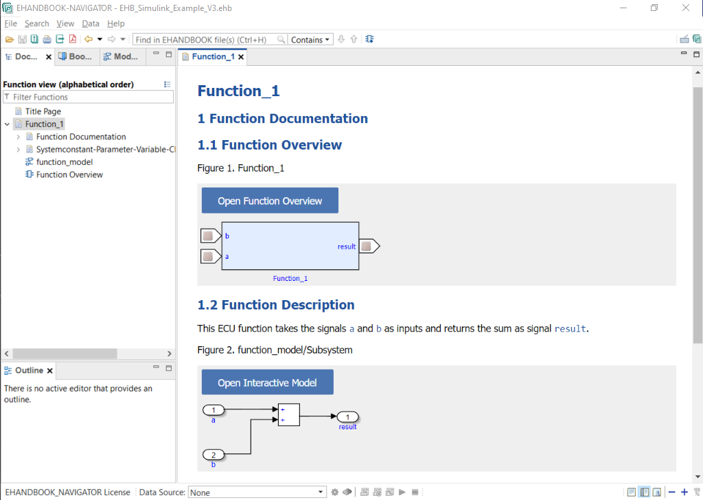
You can include screenshots of the Simulink model in the textual documentation to help explain the structure and behavior of the ECU function.
EHANDBOOK Container-Build automatically generates these screenshots from the Simulink-based interactive model.
To include a model screenshot in the documentation, add an EHANDBOOK model reference directive to your AsciiDoc (.adoc) file.
Use the following syntax:
ehbmodelref::<simulink-model-file>/<subsystem-path>[]
The <simulink-model-file>/<subsystem-path> specifies the Simulink model and subsystem from which the model screenshot is generated.
For example, the following directive generates a screenshot of the Subsystem subsystem in the Simulink model function_model:
ehbmodelref::function_model/Subsystem[]
In this example:
-
function_model/Subsystemis the model path of theSubsystem. -
EHANDBOOK Container-Build uses this model path to generate the corresponding model screenshot.
-
Replace
function_model/Subsystemwith the model path of the subsystem that you want to document.
When you generate the EHANDBOOK Container, Container-Build automatically generates the referenced model screenshot and embeds it in the textual documentation.
Generate the EHANDBOOK Container
Use the Directory-based EHANDBOOK Container-Build tool in GUI (Graphical User Interface) mode to generate the EHANDBOOK Container.
In the installation directory, double-click eHandbookCB.exe to launch the tool in GUI mode.
Alternatively, run eHandbookCB.exe from the command line without any arguments.
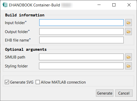
In the Build information section, specify the following:
-
Input folder:
<path>\EHB_Simulink_Example_V1\Input -
Output folder: Select the directory where you want to save the generated EHANDBOOK Container. We recommend creating an
OutputorEHANDBOOK Containersdirectory next to the input directory. -
EHB file name:
EHB_Simulink_Example_V3
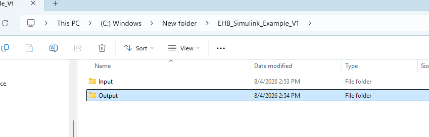
The following example shows the recommended project directory before generating the EHANDBOOK Container.
The project directory now contains the Input and Output folders. Place the required input files in the Input folder.
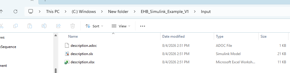
The Input folder contains the Simulink model, interface and label information, and the textual documentation used to generate the EHANDBOOK Container.
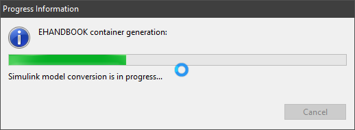
Click Generate to create the EHANDBOOK Container.
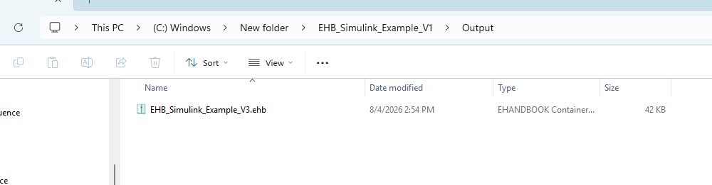
After the generation is complete, you can open the output directory or directly open the generated EHANDBOOK Container.
Open the EHANDBOOK Container in EHANDBOOK-NAVIGATOR to explore the interactive model.
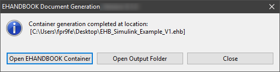
The generated EHANDBOOK Container includes:
-
The Simulink-based interactive model
-
Interface and label information
-
Textual documentation and referenced model screenshots
You can also download the generated EHANDBOOK Container here.
Explore the EHANDBOOK Container in EHANDBOOK-NAVIGATOR
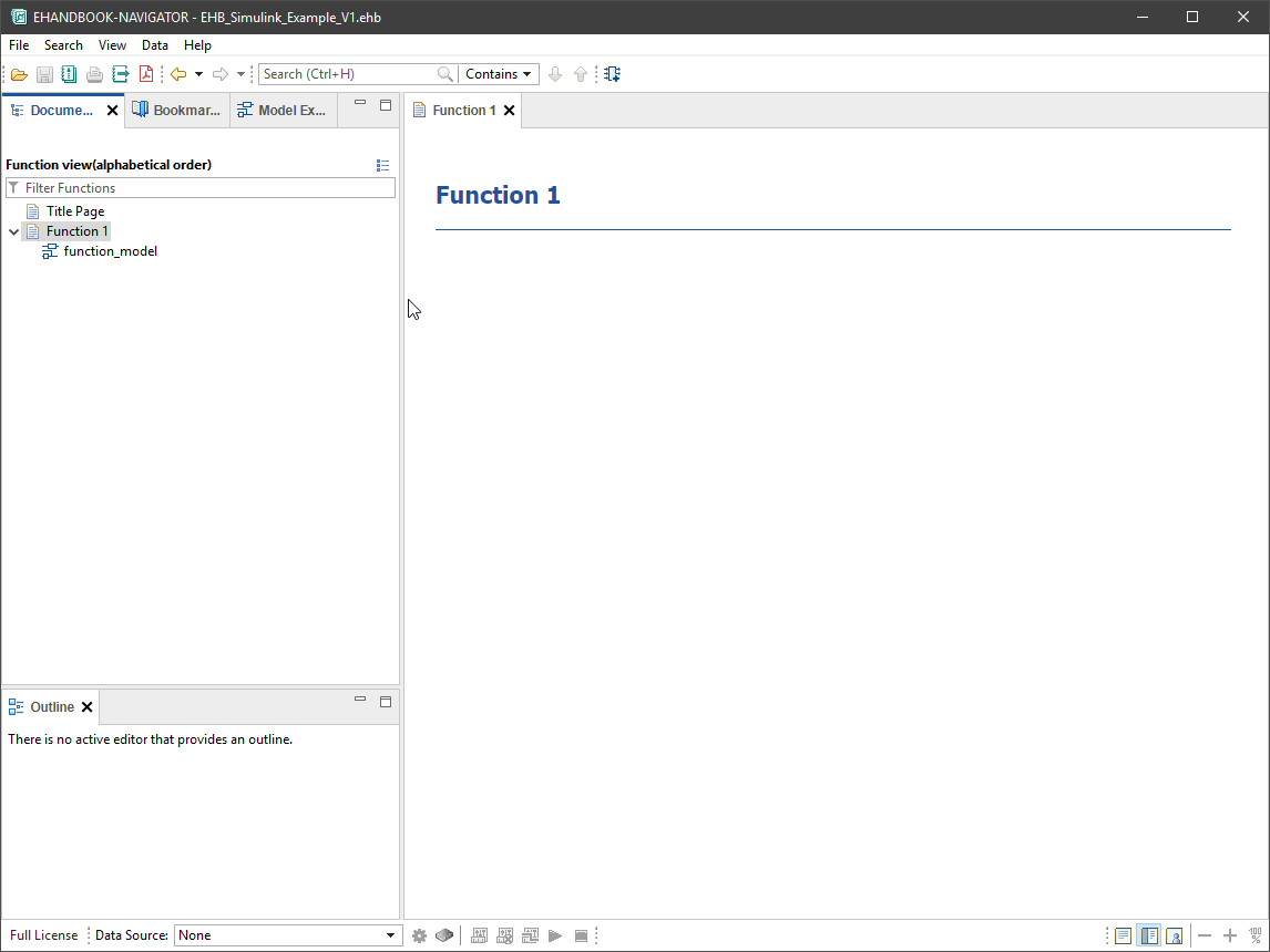
Open the generated EHANDBOOK Container in EHANDBOOK-NAVIGATOR.
The EHANDBOOK Container contains one ECU function, Function 1.
Basic Interactive Model
Expand Function 1.
A sub-entry for the interactive model is displayed.
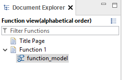
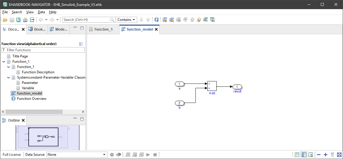
Click the sub-entry to open the Simulink-based interactive model in a new tab.
The interactive model resembles the original Simulink model. At the root level, the top-level subsystem is displayed.
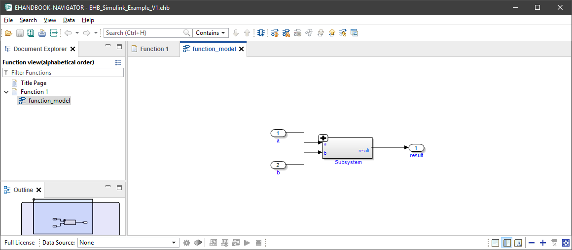
Click the + button to expand the subsystem.
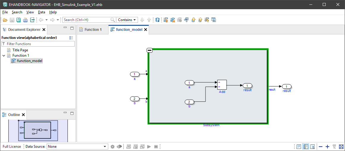
EHANDBOOK-NAVIGATOR expands the subsystem and displays its contents in the current context.
Click the Auto-Layout button on the toolbar or select Auto Layout from the context menu.
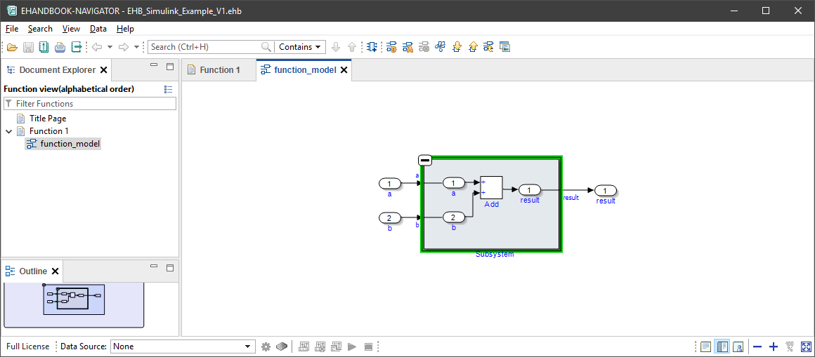
The diagram is automatically rearranged to provide a cleaner layout and a seamless signal flow across subsystems.
When you switch to the Model Explorer, you can inspect the complete ECU function hierarchy as a tree view.
Interface and Label Information
The documentation also includes the interface and label information that was added using the Excel file.
The signals and calibrations are documented as structured tables.
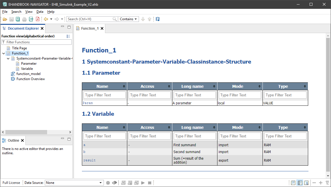
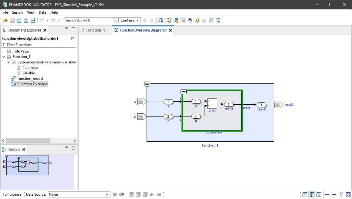
Double-click Function Overview to open the external interface of the ECU function.
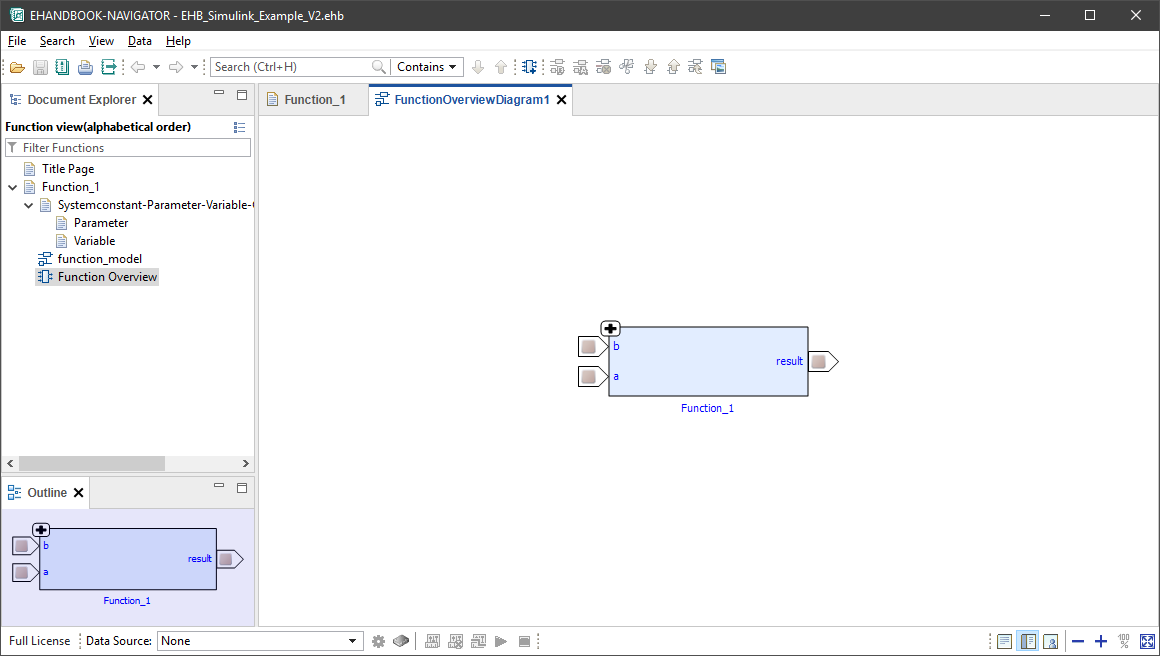
Expand the function overview block to explore the Simulink-based interactive model.
The input and output signals are connected through the label ports, allowing the ECU function to exchange data with other ECU functions.
Summary
Congratulations! You have successfully created a complete EHANDBOOK Container for an ECU function modeled with Simulink.
During this tutorial, you learned how to:
-
Generate an EHANDBOOK Container from a Simulink model.
-
Add label information and interface specification using an Excel file.
-
Add textual documentation using an AsciiDoc file, including references to Simulink model elements.
-
Explore the generated EHANDBOOK Container in EHANDBOOK-NAVIGATOR, including the textual documentation, structured tables, Function Overview, and the Simulink-based interactive model.
Now you can continue with the following tasks:
-
Create EHANDBOOK Containers for additional Simulink models. You can load and combine multiple containers in EHANDBOOK-NAVIGATOR.
-
Create a single EHANDBOOK Container containing multiple ECU functions by adding additional function directories and running EHB-CB again.
-
Generate a PDF documentation for your EHANDBOOK Container using the
-pdfcommand-line option. -
Apply custom styling and branding to your EHANDBOOK Container.